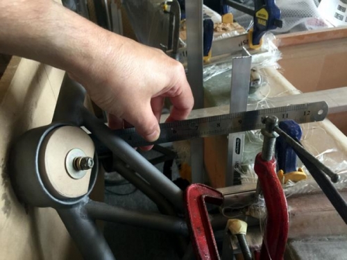
Dry fitting the mount started to get serious. Pic 1 shows I've added a couple of reference extrusions to the back side of the spar. These work really well to check the mount distance top and bottom from the back board, the datum for the back of the mounting cups.
I spent quite a few days trying to see where the plans measurements were coming from. That 2.2 degree ref was my misreading the plans as it was a top view, not a side view. However the 2 degrees nose up is correct and mentioned in the CP's. The plans measurements give 1.1 degrees at the engine mount. I'm going with this, its in range and I suspect the 2 degrees stated is a 'resultant' angle including the airfoil and incidence angles of the lifting surfaces. I've gone around a big painful circle and arrived back at the printed measurements on p15 of the engine install plans.
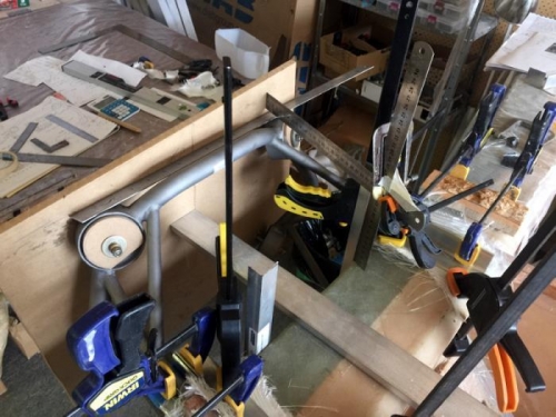
Pic 2 shows one of the ways I ensured the mount is centered. Plumb bobs were involved and anything I could think of. In the end after days of fiddling I found 12 plys of glass were needed to get things sitting right. The plans suggest 10 and not less than 7. It just has to fit. My spar width is about .1" thinner than plans too. So its a 'custom fit'.
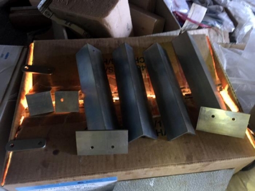
Pic 3 are the aluminium pieces drying after I alodyned them. I scuffed up the surfaces with 360 wet and dry and then the process I understand helps the epoxy adhear. Lets go with that.