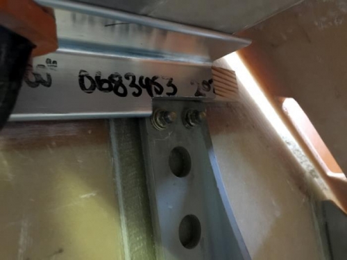
Yesterday and today I tackled this mounting business again. I'm slowly narrowing down techniques for getting the mesurements accurate. Pic 1 shows that I had to trim the lower mounts back to the plans 1" width so they can locate under the gear mount. Seems fair.
The aluminium bar in the pics is lined up with the centerline of the plane and sticks out 9.2" from the firewall. This works pretty well as I can then put the backboard on the mount and get a distance that way. I'm aware that top to bottom needs that 2.2 degree change, possibly .5" or so, but for now its an OK datum for initial dry setup.
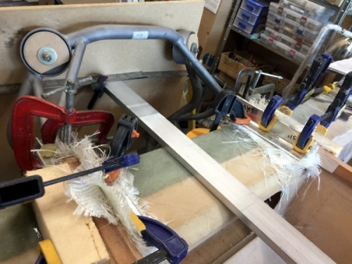
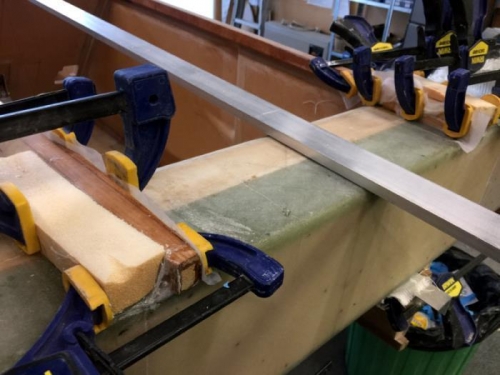
Pic two shows I've cut 40 pieces of dry glass (10 per mount) to use as fillers and then played around with the measurements to get the mount the correct distance from the spar and in the middle.... I trimed my wooden backing and got that sitting better to hold the mount so I can get a ruler to a datum rather than just handing it all in the air. I have the fuselage leveled too so that I can use plumb bobs as well. You might see in pics 2/3 that I have a bit of yellow foam on the fuselage, this is 5mt glued on so I can apply a bit of clamping pressure to the curved outside of the longerons. It makes the whole thing easier.
Once happy that I'm in 'range' I made adjustments to the spruce 'spacers' and I've floxed them in place. I seem no problem with doing this now and its just one less thing to move around when I'm getting my measurements and eventually floxing it all for real.