Brief Description: Wired Nav/Pos, Strobes, Landing/Taxi to connectors
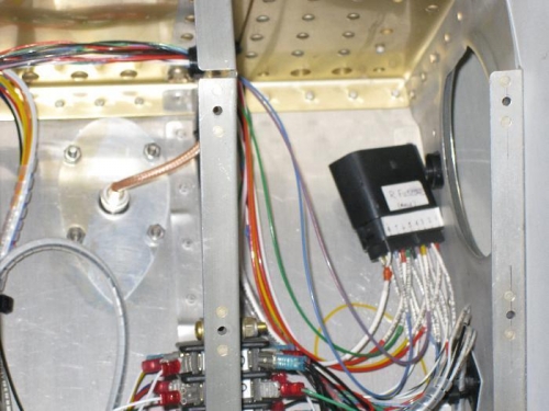
The final wires to the right and left fuselage-to-wing connectors consisted of the Nav/Pos and Landing/Taxi circuits. I had previously pulled the wires to the connectors but had not crimped and inserted the pins. These wires were all 18AWG along with the strobe wires being shielded. The strobe wires were the first wires that I had crimped, to check whether I could pass the shield braided ground wire through the connector. The shield has its own pin and will connect to the wing connector shield to ground any noise to the wing tip.
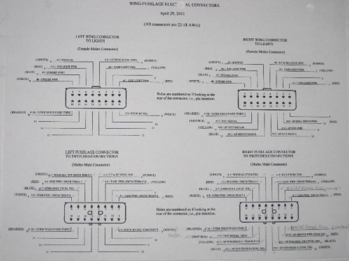
The labeling of the wires consumed most of the time while the actual crimping is easy but tedious. The left connector has 9 wires while the right has 16 wires.
The right fuselage-to-wing connector has 16 wires.