Brief Description: Added servo and avionics pwr switches.
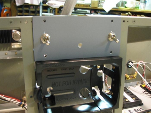
I added a couple of switches that I had forgotten about. The avionics switch and the servo power switches were added at the top of the radio stack in the small panel that will also contain the LED warning lights.
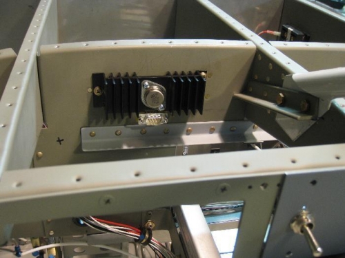
The dimmer potentiometer hole was also added in the middle of the panel. The heat sink for the dimmer was added to the left front side of the subpanel to make it easy to get to by removing the left side modular panel plate. It is held to the subpanel with #8 screws and nutplates. The wiring path to the top panel of the radio stack is short, therefore, adding more instrument lights to the dimmer should be easy.
The left switch is the avionics fan switch while the right switch is for the servo power.
The dimmer heat sink and regulator is on the left subpanel.