Brief Description: Wired pitot heat switch and determined wire gauge.
We had to determine what AWG wire was to be used for the Dynon pitot heater. I ran a string through the path from the wing root to the center spar pass through holes, up the tunnel to the FW, up the right FW angle, then back to the switch subpanel to the pitot heat switch. It was 9' and was added to the 7' from the pitot heat mount on the left wing to the wing root which gave 16' total for the wire run. Dynon says to use 14AWG up to 16' and 12AWG over 16'. So Charlotte and I wired the pitot switch from the Main bus with a 20" length of red 14AWG wire. It will be quite a bit later before we can wire the switch to the pitot in the left wing.
We also spent a couple of hours determining the pitot tubing path to the Dynon EFIS. We finally replaced a couple of snap bushings at the wing root and through the double spar panels just inside the wing root area. This will allow the two tubes (pitot tube and AOA tube) to run through the same holes together at the root then through the spar and come out through the left main gear weldment then up the left side vertical next to the pilot's knee, and up behind the instrument panel where they will be connected to the EFIS's (D180 on the left side and D100 on the right side). The left wing wires will pass behind the spar and then turn forward through the center spar electrical holes, under the fuel boost pump through the tunnel to the FW and then up and back, etc. Enough for a Sunday!
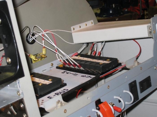
The red 14AWG coming off the Main bus to the pitot heat switch.
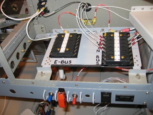
The red wire connecting to the red booted pitot heat switch.