Brief Description: Drilled rudder assembly support brace and more.
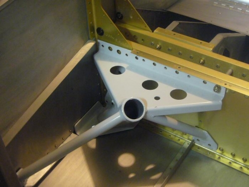
We clamped the rudder assembly support brace to the left firewall stiffner where the firewall recess panel attaches. We measured out 5 holes to drill that would not interfere with the rivets of the recess panel. I drilled out the brace holes on the drill press and then clamped it back on the stiffner and match drilled. We then clecoed the support brace to the stiffner and then I match drilled through the rudder assembly middle plastic block (the block in two halves) into the support brace flange. We did this for the three positions that we had drilled into the longerons to hold the end blocks. Charlotted deburred all the holes and scuffed the brace to prep for priming later.
We then tried to fit a gear socket weldment into the oval holes in the bottom skin that I had cut before. They would not fit, therefore, I had to use the die grinder and carbide burr to slightly enlarge the hole (3 times). We finally got the right gear socket weldment (WD-721-R) to fit against the spar and fuselage side. I'll have to ream the bolt holes in the socket fixture for a slip fit for the bolts that hold it to the spar and match drill through the fuselage holes into the weldment flange for bolts. We're not installing it now, just making sure they fit for later install.
Charlotte located all the bolts, nuts, and washers which will save time when we do install.
Rudder assembly support brace drilled and ready to install later.