Brief Description: Prep for wiring EMS GP circuits.
The EMS(Engine Monitor System) of the D180 has three General Purpose (GP) inputs that can be wired to sensors. I used GP1 for pitch trim position, GP2 for aileron trim position, and GP3 for flaps position. The EMS will show their positions once programed.
The trim sensors are built into the Ray Allen (RA) servos (which came in Van's kit) and output the signal using three small wires (26AWG) that are intended for the RA led indicators. I will use the three wires to input the indications to the EMS instead. I bought the an RA Pos-12 position sensor for the flaps which I have already mounted. I also bought the RA cable that contains the three sensor wires and two power wires. I pulled the cable to the aileron and pitch servos. The flap sensor cable had already been pulled and wired at the flap sensor. The power wires won't be used for the trim servos and flaps because the Safety Trim and Flap module wires supply the power, but the indicator wires will be used. The flaps position sensor has only the three wires.
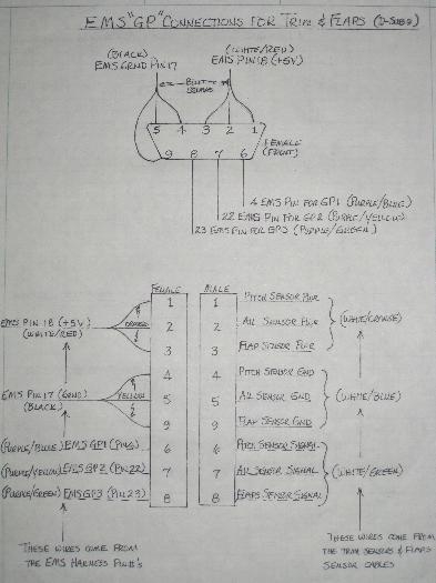
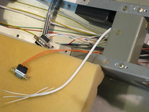
The picture below is a hand drawn diagram of a D-sub 9 that I will use to make the connections to the EMS harness wires. The second picture shows the aileron D-sub connectors. The orange power wires in the second picture come from the Safety Trim module. I'll wire the pitch trim connector when I install the empenage.
D-Sub9 connections.
The cable pulled to the aileron servo. The bent back white wires will be cut off.