
|

|
|
|
KENNETH T.'S WEB SITE
|
Date: 1-14-2011
|
Number of Hours: 6.00
|
Manual Reference: Intcom schematic
|
Brief Description: Wired intercom audio input wires.
|
|
I decided to wire the audio inputs to the intercom by using a D-sub9 connetor. The female side holds the 220 ohm resistors that had to be added the input wires from the Com, Nav, and HS34 audio alarms. The three input wires insert into the male connector at pins 1, 2, and 3. After inserting the resistors into the female connector, the audio input wires come out of the male connector at pins 6, 7, and 8. A spare resistor was installed on pins 4 and 9 for later additions if needed. The input wires were twisted and then butt crimped to the blue intercom signal input wire
The resistors were small which allowed me to crimp the female sockets to their wires and insert them into the female connector. I thought this would make for easier troubleshooting later by not cutting crimped connections.
The Com Mic Audio Hi and Com Mic Key wires were butt crimp connected to the intercom brown and white input wires respectively. All the Lo (ground) wires were inserted to the D-sub25 avionics ground bus that I had previousl fabricated.
|
|
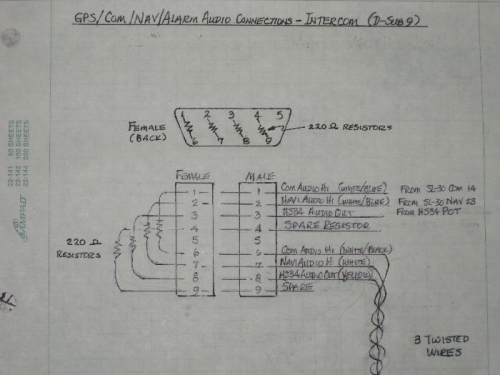
D-Sub9 wiring of resistors to Com, Nav, & HS34 audio for input to the intercom.
|
|
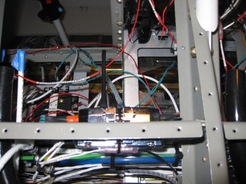
D-sub9 back-to-back with DSAB connector on the subpanel
|
|
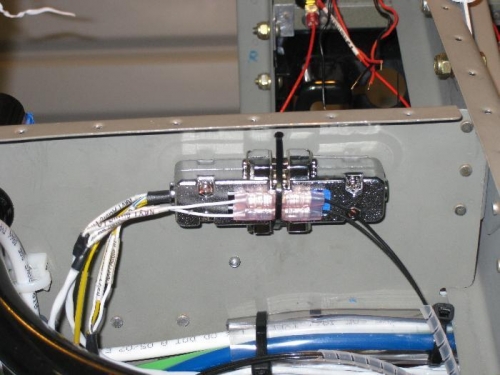
Looking aft, the d-sub9 connector for audio input to the intercom.
|
|
|
|
|
|
|
|
|
Copyright © 2001-2024 Matronics. All Rights Reserved.
|