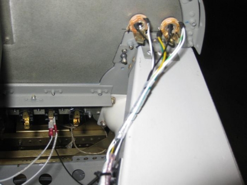
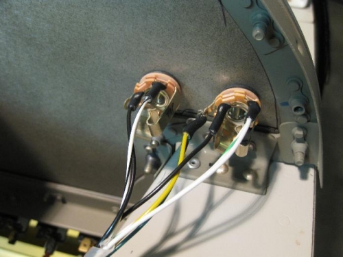
Today I wired up the pilot's and copilot's headset jacks. Soldering is not what I call fun, but it is a necessary skill that I've learned to tolerate. The intercom output wires were soldered to the headphone jack at the ring and tip, and then wires were run cross-cockpit to wire the same connections on the copilot's jacks. The mic jacks each had only one intercom wire to connect at the ring. All the jack's barrels (grounds) were isolated from the chassis using the shouldered insulated washers to prevent ground loops. All the barrel grounds were run to the avionics ground bus.
The pilot's jacks are on the instrument panel while the copilot's jacks are below the canopy rail. I had to allow a service loop for the pilot's jacks in the event I have to remove the modular panel. No service loop was required for the copilot's jacks. Without the schematic that I had drawn, I would have been lost with all wires running here and there. The continuity checks were all good. Unbelievable!!