Brief Description: External Steps 2. Why doesn't it fit correctly?
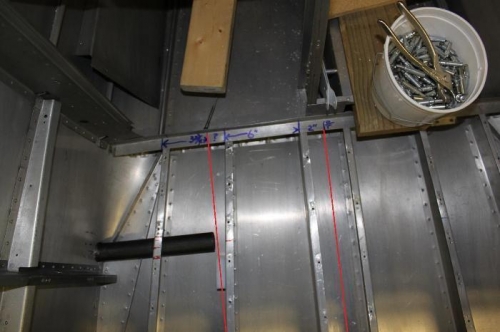
I have nothing but good to say about Ken at Vans Aircraft. He asked me to check some measurements and sure enough, the reason the step tube is so far away from the F626 floor rib is because the floor rib was installed at the wrong location by the quickbuild factory builders, whomever they were. The web of F626 should be 9 5/8 from centerline of airplane, or put another way, should be 3 3/4 to the right of the outer most rib web back at the F606 bulkhead. On the center photo I drew a red line for centerline and another red line for where F626 should be. Instead of 9 5/8 from center, these two F626 (one on pilot side and one on copilot side) are 8 inches, or 1 5/8 inches inboard of the plan location back at the F606 bulkhead. We are examining several possible fixes and will wait for Van's engineering input. Not a major problem. I have plenty more to do. I ended up shipping the steps back to Vans so they can weld the tubes to the required lengths for installation. Basically the length of the tube from the attach plate to the end of the tube at midline of the circle (forward side) is 10 7/8 inches and at midline of the circle on the aft side is 11 1/8. That is 1 inch and 1 1/4 inch respectively longer than the supplied tubes.
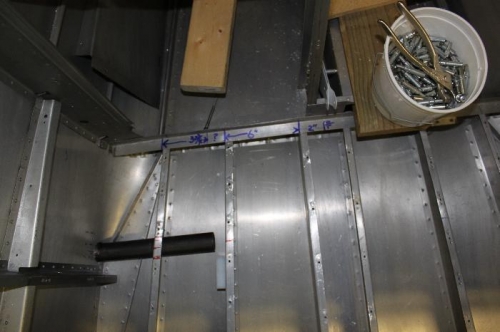
Camera fools the eye but the F626 rib is supposed to be parallel to the center ribs.
F626 web should be 9 5/8 from centerline. Left red line is proper placement.
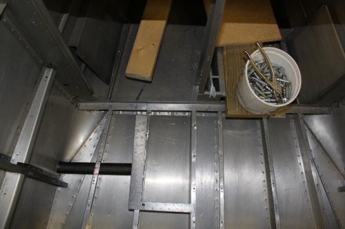
A square laid out shows where the left edge of rib should be.