Brief Description: Prime control tubes, start aileron trim parts
I primed the inside of the tubes and set them aside to dry and began to prepare the F-807 control mount. The Control Column comes powder coated but you have to drill the holes to size for the various bearings that attach to the control column. The control sticks get attached with AN4 so they are ¼” and the others are all AN3. I used a ream for all of the holes just to get the best tolerance hole I could. I also install the bearings and tightend the jam nut to the proper torque on the F-839 control rod. This is the rod that lings the two control sticks and it rides inside the main tube of the control column (F-807)
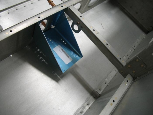
I next took a look at the aileron trim, I am going with the electric trim. Well it seems the instruction and the DWG (OP-1) for the aileron trim have not kept up with the kit. The instructions have you use a jig to drill the holes for the servo bracket and cut out the opening for the trim control rod to pass through. Well my kit has a cut out and there are pre-punched holes that align perfectly with a few key holes in the bracket (see photo). I will still use the drill jig since it is set up to drill from the more accessible side of the floor rib, but I will need to modify the cut out to match the oval hole in my floor rib, the jig comes with a smaller square cut out, also the bevel in the opening interferes with the drill jig. The entire electric trim install seems fairly simple.
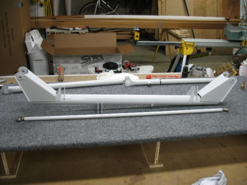
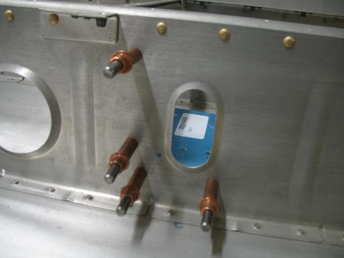
Contorl column drilled and F-839 bearings installed
Aileron trim sevo bracket cleced into 4 pre-punched holes