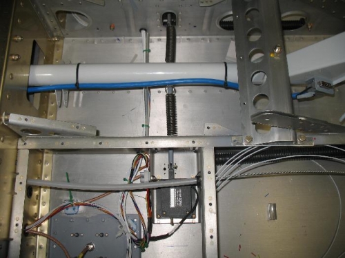
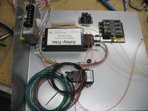
Well I thought I might get some work done Thanksgiving while cooking the turkey but I never did make it to the shop. Today was fairly productive. My order came in from Spruce, I needed more 5 conductor trim servo wire, I pulled the wire from the aileron servo to Electronic Equipment (EE) Bay which started out as a battery bay, but with all the electrical modules I am installing there I think EE bay is a better description. I installed the female D-sub pins then connected the servo and put heat shrink over everything. I needed to hook up the springs to the control column to test the trim servo, but I need to make sure the servo was in the neutral position. I hooked up a switch and the trim position indicator and ran the motor full both directions. After parking the motor in the neutral position I hooked up the spring to the control column and then ran the motor through the full range of motion, it works great.
I then found a location for the Smart Start module in the EE bay wall. I drilled holes and mounted the module the worked on organizing all of the wires that go here. The last thing I did was find a location for the terminal that will tie the servo wires to the trim system and the indicator on the EFIS. I need some smaller hardware for the terminal block so I called it a day.