Brief Description: Pulled wires for fuel quantity senders.
I realized that I had not pulled the wires for the fuel quantity connections to the resistive float senders. I, therefore, delayed putting on the gear legs so that the fuselage would be lower and easier to add the wiring.
I ran the left and right wires into the carrythru-spar and passed them through the nearest wire hole to foreward of the spar, to the center tunnel, under the tunnel cover, and then up the FW. I butt-crimped each wire to its corresponding wire (pins 20 & 21) in the Dynon D180 EMS harness. I followed up by doing a continuity check which meant I had to disconnect the EMS harness from the D180.
There is not much room behind the instrument panel to unscrew the Dsub connector. I shortened a small screwdriver by cutting off some of its handle to loosen the Dsub screws from above with good availability and visibility. Once the top skin is riveted on, I'll have to cut the zip ties that hold the harnesses against the subpanel and uninsert the tubing, all from underneath while lying on my back with a flashlight in my mouth. I'll then remove all the screws holding the left side of the instrument panel and set the panel onto the left seat where I'll then loosen the Dsub screws. Who designed this piece of crap? Oh! It was me, so I can't shoot the engineer!!
It was good that I put in a modular panel for future maintenance and this very possible scenario. Luckily, the continuity checks were good.
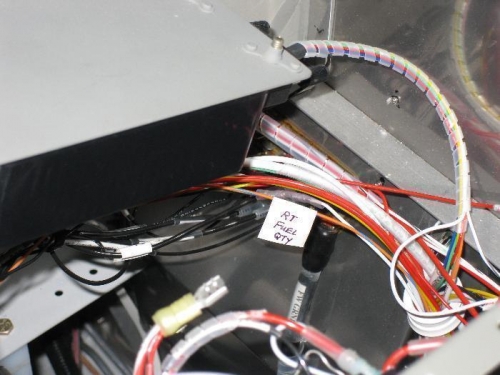
Butt-crimped the Dynon wire to the pulled wire at the FW.
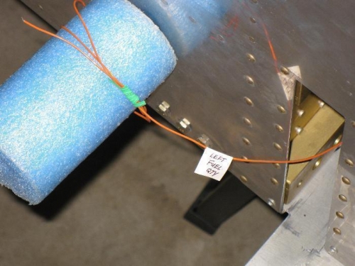
View of the wire coming out the wing spar insertion hole. The foam is covering the fuel tube.