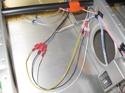
The pitot heat wiring connects the switch in the cockpit to the heat module in the wing which then connects to the pitot. I drilled a hole into the PVC conduit and ran the red power wire and a white signal wire from the wing bay to the wing root. I crimped faston connectors and then wrapped them in self-stick silicon tape to hold against the conduit. I used stick-on zip tie mounts with a pop rivet to secure the wires in the bay for strain relief and vibration.
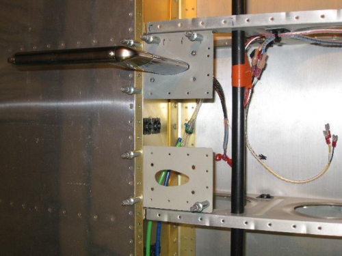
Last night I read the VAF forum and found that most people put their pitot on the rib next to the bellcrank access hole, the rib inboard of where I put mine. Something about tying down the airplane may interfere with the pitot. I decided to add a Gretz plate (with the mount hole) to the rib next to the bellcrank access hole in the event they are right. Once the skin is riveted, it should act as a doubler to strengthen the skin against movement caused by air loads on the pitot. If I later find that the pitot needs to be moved inboard, all I'll have to do is cut the mount hole in the skin and cover the other mount hole using a nutplated patch (which I fabricated) that takes the place of the mount.
Wiring connecting the heat module to the pitot.
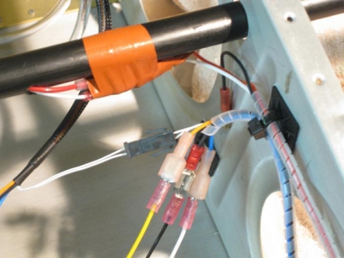
Closeup of the red & white wire entering the conduit.
This shows the extra mount plate on next inboard rib.