Brief Description: Start install of Tip on Vertical Stabilizer.
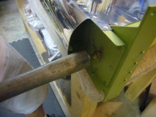
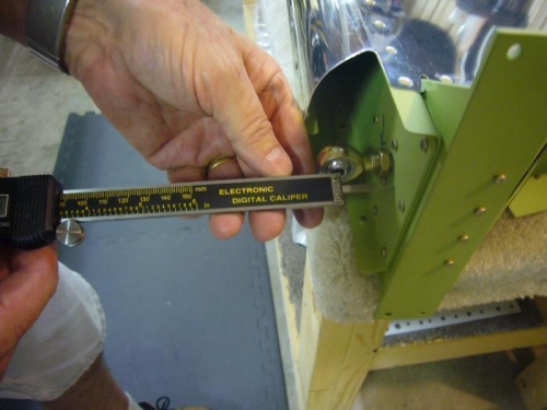
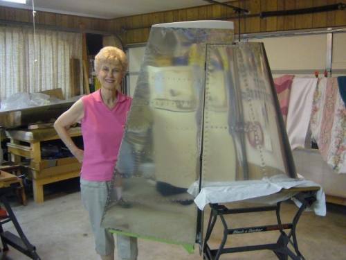
Decided to install the VS tip. We had to mount the rudder to the VS to check the clearance of the balance weight arm swing to the tip. We had to install the rod end bearings onto the rudder with the appropriate bolt-hole-to-spar dimensions. I had a metal tube that I had squashed the end on as cheater for a socket wrench. I used it as the tool to screw in the rod ends and it worked great. We set the dimensions using the caliper and then tightened the jams nuts using a open end wrench. No way to get a socket or box end wrench over the rod bearing, so I had to be careful not to slip and round off the nuts (a pain in you know where). We then tried mounting the rudder using the temporary pins instead of bolts. The middle rod bearing was off so we readjusted its dimension (twice) before we realized that the VS spar was bending at the bottom from the weight of the rudder. We had the VS sitting in the Black & Decker adjustable work table. We finally got the rudder mounted and noted that we needed to cut about 1/16" off the tip skin to get better clearance. I did the trim job using the Dremel tool after dismounting the rudder.