Brief Description: Analyzed fuselage layout (Dwg 17A) to find axis of
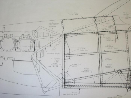
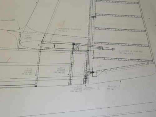
I spent some time analyzing the fuselage layout drawing 17A for the RV-7A to decide where the line of rotation should be. One must consider what height he'll/she'll be working and how this changes when the fuselage is rotated. After much deliberation with myself and my brother, we decided that if we used the thrust line as the axis of rotation it would be a good working height for all angles of rotation. I later found a website where the builder had measured down from the top longeron 13 1/2 inches. This put the axis about 3 inches below the tail end bulkhead.
I tried both and found that the thrust line axis did not allow the cockpit part of the fuselage to clear the leg of my Harbor Freight engine stand for a 90 degree rotation. I then used the 13 1/2 inch measurement down from the upper longeron and that put the fuselage 5 inches higher on the stand, but it would clear for a 90 degree rotation. If I had built from scratch I would not have the engine stand leg to clear and would have used the thrust line as my axis. My wife and I are short, 5' 5 1/2 " tall, and I would have preferred the lower working height (fuselage not rotated). But it will be OK since I don't weld and my engine stands were on sale.