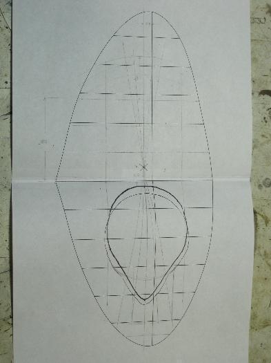
Brief Description: CAD drawing of the tip cut-out grid.
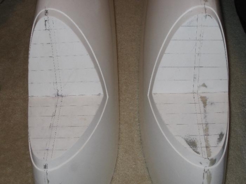
Nothing on the wingtip cutout is straight except the intersection of the cut-out faces. I, therefore, created a grid using lines measured one inch apart from the face intersection toward the tips of the faces. I then traced the mold line of the faces on to some graph paper which was creased into two halves at the intersection. From the traces, I got measurements from the moldlines to the centerline created where the fiberglass pieces joined to form the wingtip. I entered these measurements into my TurboCad program and printed a trace of the cut-outs.
Using the CAD program, I was able to insert the Aveo light measurements and overlay them onto the moldline trace including the 120 degree angle between the faces. This gave me an accurate picture of the hole needed in the angled face for the landing/taxi light with the position/strobe attached. This was the first of several iterations.
Grid lines drawn with pencil.
CAD printout from moldline measurements.
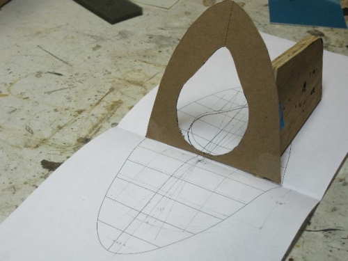
Cardboard face with the hole and face at 120 degrees.