1. Ran the left and right rudder cables from aft fuse through bulkheads forward to center bulkhead installing the snap bushings along the way. Drilled a 5/8 hole in fwd side of center bulk head but the 2 hole on aft side are more difficult to do cleanly because of a plate nut that is too close for my unibit to reach w/o hitting it. Will need to pick up a regular bit tomorrow and try. If that doesnt work, I will need to drill out the plate nuts and drill the needed cable hole and then reinstall the plate nuts.
2. Secured the aft rudder cables sleeves to the interior fuselage with a clamp in close proximity to the exit hole in fuse. I used my pop rivit dimpler with a #30 dimple die to dimple the screw hole for the clamp. This might of helped but only slightly. Realy need to use the appropriate #8 die but I dont have one for the pop riviter. It looks ok.
3. Started on the rudder pedals by drilling the #12 in the rudder slide bar and socket after they were temporarily installed to the cockpit floor and firewall.
4. Removed the slidebar and deburred. Installed the slide coller and rudder slide on the slide bar, clamped to table, and drilled for a pop rivit in the coller.
5. Put the left and right rudder pedals onto the rudder slide and tested for smooth rotations. Had some slight drag issues so I removed and cleaned up with file and emery paper and scotch brite. Greesed and reinstall. Much better.
6. Installed the nylon slide blocks and match drilled to the the slide bar on left then right. Drilled first the aft facing hole then the fwd facing hole. Took apart for deburring and then reassembled.
7. Match drilled 1/4 the lock pin hole in slide bar full fwd position and then full aft position. Took apart and deburr. Scribed more holes for the lock pin every 1 inch betwen the previously drilled holes. Once again disassemble and deburr then reassemble.
8. Drilled the holes for attaching the brake pedals and brake cylinders. Also sanded the brake pedals with med then fine scotch brite pads. Will prob
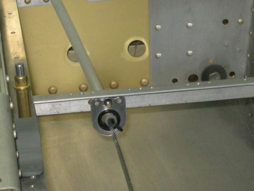
Rudder cable fwd support. Note the cable tie inserted through drilled hole in sleeve
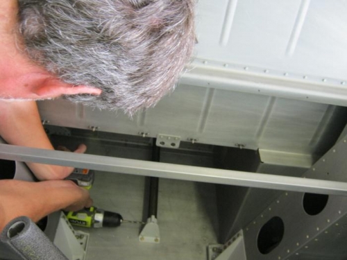
Match drilling the rudder pedal socket to the slide bar. Both are temporaily mounted
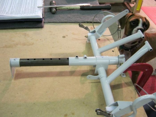
Rudder pedals and air adjustable slide bar drilled, lubed, and assembled