Brief Description: Control column, push tube, control sticks
1. Marked drill location on the right elevator horn and drilled #40 followed by #12.
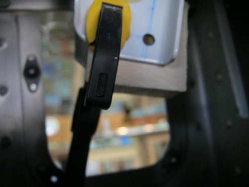
2. Cut a peice of hard wood to fit between the 2 elevator horns and then marked hole location on it through the previously drilled hole.
3. Drilled the hole to 3/16' on the drill press and then used it to guide and match drill the left side elevator horn. Removed the block and then deburred the holes.
4. Rivited the threaded end bearings onto the f-840 push tube with six msp-41 pop rivits on each end and then primered.
5. removed on a slight taper material from 2 brass bushings on belt sander until the bushing fit in the front and rear control column for the control sticks.
6. Reamed the bushings to 1/4 inch.
7. Installed the bushings in control sticks and bolted to the control column with an4 bolts and torqued to 60 inch pounds. I had to remove several times and work the bushing and control stick until I could torque it to 60 while keeping a free moving action.
8. Attached the rear upper stick to the base and drilled for a retention bolt #12 per drawing 79
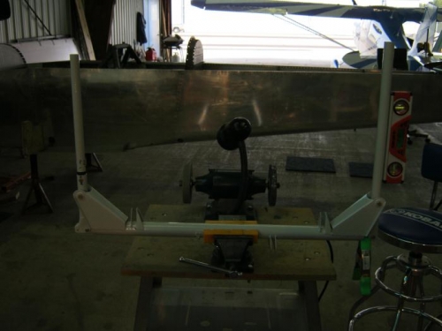
9. Installed the F-839-2 push rod assembly through the control column and adjusted the length with the end bearings until both control sticks were parallel with each other. Snugged up the lock nut when both were parallel. Grinded down those bolts untill there was enough clearance on the control tube wall without possibility of catching on it.
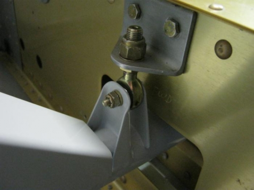
10. Removed the sticks and installed the control column in the fuselage mounting it to the front and rear control mounts with rod end bearings. The front rod end was adjusted verticaly to 1 inch and the rear to 7/8" as per drawing 77 and 79
11. Reinstalled the control sticks
Notes:
1. Instructions called for mounting the aft control mount to the floor skin but I didnt want to put the floor in for this yet. I used to thin washers to put under the rear mounting bracket to simulate the skin thickness.
2. The forward control mount is installed by Vans already and secured with lock tight. Only problem
Wood drill guide clamped in position between the elevator horns
Control column and control sticks parallel with each other.
Control coumn installed in the fuselage and bolted to the front and rear rod end bearings