Brief Description: Wired Tach Transducer to RPM Wire and Power
Calls were made to UMA Technologies, Dynon, and finally Jason-Aerotronics re the how-to on wiring the tach transducer and the Dynon RPM wires. The Dynon EMS requires that the transducer provides 10V minimum. UMA confirmed that it will provide a range of 5-25V and that it works well with the Dynon units. Jason confirmed for me that the transducer is the only thing needed for displaying RPM. The tach transducer still measures the magnetic pulses if the magneto is switched off, such as when the key switch is turned to the electronic ignition position.
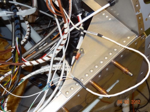
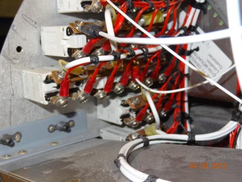
The transducer wire is a 3-conductor shielded wire. It was run under the instrument panel ribs and wrapped with other wires. The power wire from the Lightspeed was also wrapped toether and run to the right side of the panel. The transducer wire had the cover stripped off and the three wires were removed from the shield. The shield was shortened and had another wire soldered to it. This wire was crimped onto a ring terminal, along with the ground white/blue wire. The white wire serves as the sending wire and was solder-crimped to the #32 RPM Left wire, which had been shortened. Another length of 20 AWG wire was solder-crimped to the power white/orange wire. The other end of the wire had a ring terminal crimped to it. This terminal was screwed onto the bus bar behind the EMS CB.
The tach transducer wire and the Lightspeed wire running to the right side of the cockpit