Brief Description: Pulled P1 Wire off Master Relay/P-Lead/Connectors
I realized that the P1 wire did not have to be used. This wire had been screwed onto the master relay and then run thru the firewall and the tubing up the firewall, along with the P3 and K1 wires. The Van's plans showed that the P1 wire would be used, but the Aerotronics' plans did not incorporate it.
UPDATE, 9/23/11: After talking with Jason-Aerotronics, I learned that the P1 wire should be used and run from the Master Relay to the Battery side of the Alternator CB. This will allow the Master switch to turn on the panel. The current method of wiring does not allow the battery to provide any power to the panel without the alternator operating. A few changes need to be done to the ammeter shunt wiring.
The P-lead was wired to the left mag.
UPDATE, 9/23/11: Per Jason, the ground made using the shield of the P-lead does not need to be attached to the mag. This should be cut off and only the 18 AWG wire screwed to the mag. The mag is grounded after the P-1 connector.
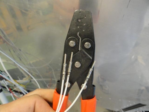
Three wires that will be inserted into the P-1 connector had the Molex connectors crimped onto them. The center section of the connector was crimped using the D hole in the crimping tool and the barrel end of the connector was crimped using the A hole.
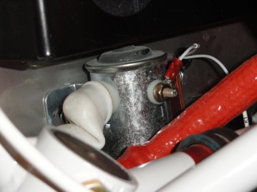
The master relay with the P1 wire removed
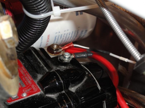
The P-lead screwed to the left mag
The Molex crimper with the first three wire connectors crimped for the P-1 connector