Brief Description: Rudder Pedal Correction/Reposition Comm Antenna
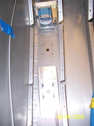
I pulled the rudder pedals out of the fuselage and took off the right pedal on the left side. I started to drill out the side bracket in order to correct the angle. I used a 1 3/8'' hole cutter in the drill press to drill three lightening holes in the F-611B bracket. I drilled pilot holes in the left comm antenna bracket and then drilled the bracket in place approximately six inches aft of its original spot. This was done in order to properly position the roll servo in the left bay. All holes were deburred and then dimpled with the pop-rivet dimpler. I installed the aileron control rod to the control stick, along with the roll servo attached. There might be some interference between the two control rods, depending upon the position of the roll servo.
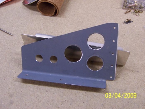
Lightening holes drilled in the F-6111B bracket
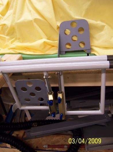
The right rudder pedal, left side, removed for a new side bracket