Brief Description: How to setup Wing Core and CS Spar positions 3
3.1 Setting up the CS spar on the floor now we have the lower wing in place. BTW the spar should be completed up to pg 14-2 and the end of step 5 and no further. Note that the spar cap depth and other areas will be changed so approximate depth is OK. Note that the spar caps increase in thickness at BL 0, get thinner then thicker and twist towards the ends to 'fit' to the wing.
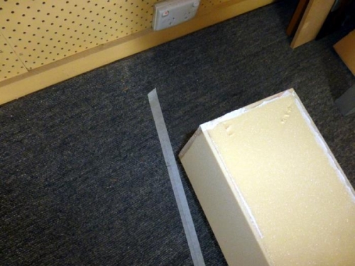
3.2 Note position of CS spar pg 19-10. Lower corners are BL 55.5 and BL -55.5 and FS 130.5. Now see pg 19-12 section B-B there is a gap for the inserts (AN960-816L) collars as well as some glass buildup beyond the foam cores we have now. Allow .6" (.5" if you like.) The thing is to have a consistant gap so that the bolts when they are fitted are parallel or at right angles to the wing and the spar and the same distance apart.
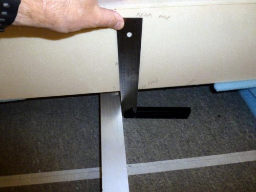
3.3 Set up the CS spar at BL 55.5/-55.5 and FS 130.5 less 0.6" = FS 129.9 Take particular care to get BL 0 parallel to the floor tapes using a straight edge and square. Note there will be a slight gap if FC1 is in place, so thats a good check. The CS spar must be high enough to be very close to the spar troughs matching FC2/3 in height. This is about 5" at BL 0 off the ground.
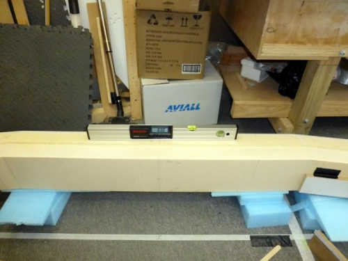
3.4 Level the spar with the digital level you have, recheck the position