Brief Description: How to setup Wing Core and CS Spar positions 1
In this series of entries I will document the proceedure for setting up the wing cores, right wing first, relative to the CS spar and correct positions per the plans. We already have FC4/5 and FC2/3 completed with FC1 (three pieces per wing)
The goals are:-
A. Set FC1 at the correct angle to the CS spar and glue in place B. Determin the CS Spar required thickness relative to the wing cores. C. Ensure the CS spar is trimmed so that the spar caps end up the same height or lower than the wing.
page 19-10 has all the critcal measurements and this is the main reference and needs to be refered to at all times.
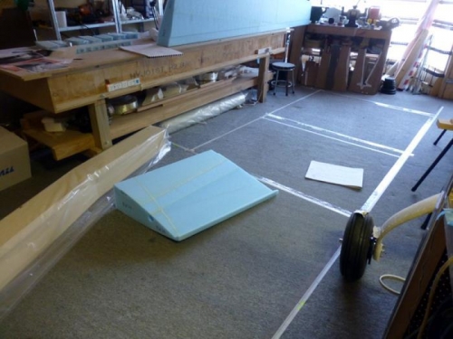
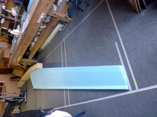
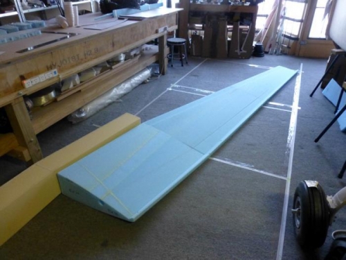
1.1 Draw a grid on the floor using masking tape. Mark out lines BL -55.5 to BL 160 long and FS 110 to FS 180 (width axis). This will be long enough to include the spar and the wing foam blocks FC4/5 and FC3/4 and FC1. Check the right angles and mark on the tape similar to the edge points on pg 19-10 like FS 176, BL 157 and FS 130.5 BL 55.5.
Carpet is not ideal but it still works. It doesn't really matter if the floor is uneven.