
|

|
|
|
Des' Web Site
|
Date: 2-6-2023
|
Number of Hours: 0.00
|
Manual Reference:
|
Brief Description: Backbone Wiring Part 2
|
|
Continued:
An instrument panel mounted circuit breaker will control a relay that can disconnect the integrated generator from the main wiring system if required. This relay will automatically disconnect when the master switch is OFF in order to prevent the main battery being drained by the voltage regulator. The field of the external alternator will be powered by the VPX system with an instrument panel mounted switch providing ON/OFF control. By virtue of system design, the voltage regulators are set at different levels allowing both “generators” to be connected to the bus at the same time. In the event of a VPX failure, the external alternator may lose its field power, load shedding may be required when operating on the integral generator only.
Bus architecture:
There are 2 buses, Main (VPX) and Essential (E-bus).
The main bus is the VPX which handles all non flight critical loads plus flaps & elevator trim. There is no redundancy for flaps & trim, if a failure of VPX or main power supply is encountered, flaps & elevator trim will be stuck in their positions at the time the failure occurred. There are many advantages of operating these controls through VPX & in my view, the advantages out way the risks of an unlikely VPX failure.
The E-bus is powered by one of two different sources,
1. When the master switch is ON and the E-bus/VPX backup switch is “NORMAL”, directly from the master contactor via a diode or
2. Any time the E-bus/VPX backup switch is “ON”, directly from the main battery via a circuit breaker & relay.
With the E-bus/VPX backup switch to “NORMAL” the E-bus powers the “Aux” fuel pump via a circuit breaker & switch plus the engine Turbo Control Unit (TCU) via a circuit breaker.
With the E-bus/VPX backup switch to “ON” the E-bus additionally powers the radio & propeller controller via their respective circuit breakers (& prop switch).
Voltage monitoring of the E-bus is displayed on the G3X system & system testing will be possible before engine start.
|
|
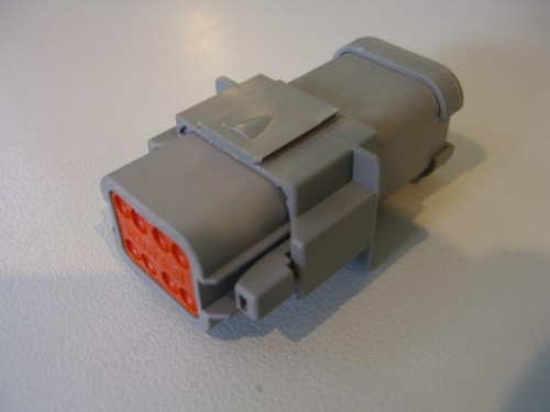
E-bus (8 contacts bused internally)
|
|
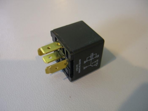
Relay
|
|
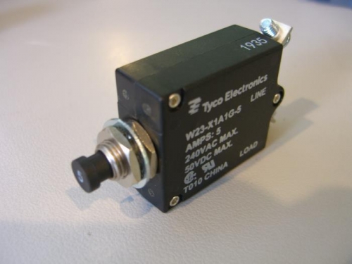
Circuit breaker
|
|
|
|
|
|
|
|
|
Copyright © 2001-2024 Matronics. All Rights Reserved.
|