This very long log is intended to be a statement/record of the reasoning behind the electrical system I have chosen to install. This log has 2 parts.
This aircraft will be registered for flight "Under the VFR by DAY ONLY". It has a single engine, a single engine monitoring system, single pitot probe, single main battery & 2 electric fuel pumps (one of which must be operating for the engine to run - no mechanical fuel pump). It also utilises an electric constant speed propeller system. I accept this aircraft relies significantly on electrical power & there are numerous potential single points of failure in this type of aircraft/engine combination that are almost impossible to sensibly avoid. With those limitations in mind, I have attempted to design a wiring scheme that can accommodate many failure modes without being overly complex or heavy. Numerous sensors will monitor the electrical system parameters with indications & warnings displayed via the G3X system.
Flight instruments/engine monitoring: The installed Garmin G3X flight instrument/engine monitoring system has a backup battery that will provide up to 55 minutes operation in the event of loss of primary power. The MFD switch is required to be OFF to achieve this duration. The Autopilot is NOT available on backup power. The installed G5 flight instrument has a backup battery that will provide up to 240 minutes operation in the event of loss of primary power. An alternate source of static air pressure is provided for both flight instrument systems.
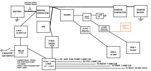
Electrical power generation: I have elected to follow the published wiring scheme depicted in the ROTAX 914UL installation manual including the optional 40 amp "external alternator". This scheme utilises a master contactor & has the 20 amp "integrated generator" operating at all times the engine is operating. The "Main" fuel pump is powered via a circuit breaker and switch directly from the integrated generator output.