
|

|
|
|
Terrences Web Site
|
Date: 1-31-2008
|
Number of Hours: 2.50
|
Manual Reference: 6W6 4-6
|
Brief Description: Drill & cleco bell crank support channel
|
|
1. Draw a line down the middle of the bellcrank support channels, 6W6-10, and a line equidistant between the pilot holes for the channel on the rear ribs #7.
2. Position the bell crank support channels on the ribs(L&R), aligning the channel center lines with the line on the ribs; mark the edges of the flanges at each end of the channel.
3. Draw lines 4-mm from and parallel to the flange edge lines on each end of each channel.
4. Trim each channel end with snips and file smooth. Trim flange ends to 45°,
5. Clamp each channel to its rib & back-drill & cleco 3/32" through the pilot holes in the rbs. See Fig. 1.
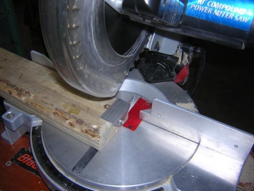
6. Use chop saw to cut the flanges on the aileron bellcrank supports to the required 20-mm width. See Fig. 2. I screwed the supports to a scrap 2x4 to immobilize the support while sawing. I should have used the chop saw to make the other cuts on the supports. It is much easier, once one provides adequate support.
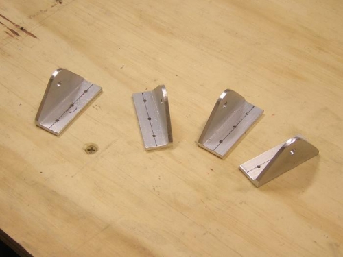
7. Drill 3/32" pilot holes in the bellcrank support flanges. See Fig. 3.
8. Rereading the PAM 6W6 p. 3, I realize that I failed to clamp the bellcrank supports together before drilling the 3/16" hole. So, I bolted the the supports together in pairs to make sure there is adequate alignment between the two supports. I found that the verical alignment (i.e., the alignment of the base of the flanges) was essentially perfect, while the horizontal alignment was off ~1-mm. Since the supports will be bolted together before drilling and clecoing, that should remove any problem
LESSON LEARNED: Always reread the PAM instructions word for word, very carefully, before cutting metal.
|
|
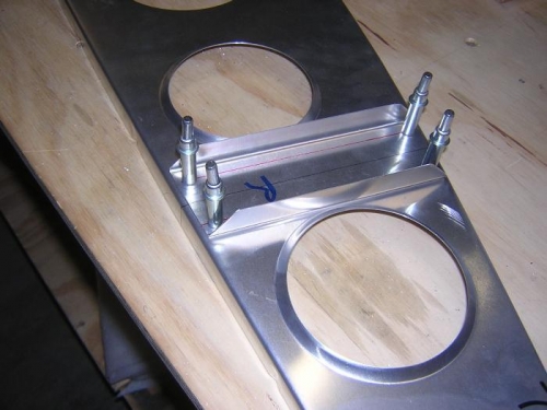
Support channel
|
|
Bellcrank supports
|
|
|
|
|
|
|
|
|
|
|
Copyright © 2001-2025 Matronics. All Rights Reserved.
|