
|

|
|
|
Terrences Web Site
|
Date: 1-26-2011
|
Number of Hours: 6.00
|
Manual Reference: 6-ZU-4-10
|
Brief Description: Install R aileron counter-balance arm & ribs
|
|
1) Choose the location for the balance arm installation
a) ~227 mm outboard of the 3rd rib, but placed to utilize existing top flange holes
b) Make sure I get the 87° angle correct
2) Mark and drill the holes top and bottom, leave the front holes undrilled for now. I think it will be easer to drill while the aileron is still tightly riveted.
3) Cut the hole for the balance arm
4) Drill out the flange and rivets for the two end ribs—Avex rivet removal insights
a) Two layer joints are no problem
b) The rivets tend tohang up in joints of three or more layers. The following appears to work with A4’s:
i) Drill rivet head 1/8” until it spins free
ii) Use a 3/32” pin punch to separate the rivet from the top layer
iii) Drill the rivet stem 1/8” until it separates from the bottom layers
iv) Trying to punch the rivet stem from the bottom layers after i) just bends the base metal
5) Drill out the control horn rivets
6) Pilot drill the inboard balance arm rib rib through the pilot holes
7) Cleco rib in place, then measure and drill pilot holes for the front rivets
8) Remove the rib, mark and drill to the control arm
9) Clamp and drill inboard rib and balance arm to the outboard rib
10) Drill the outboard rib for the weights.
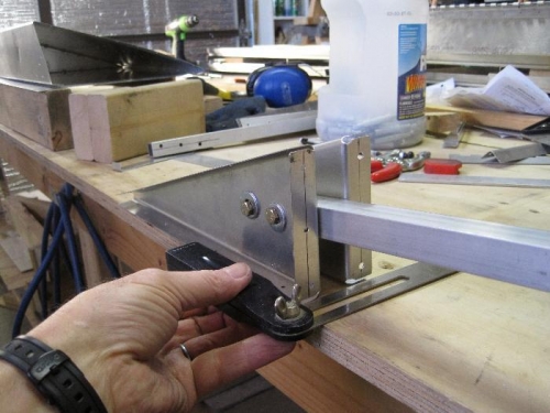
11) Cleco the inboard rib to the aileron, bolt on the balance arm and outboard rib
12) Pilot drill the outboard rib to the aileron skin, top and bottom. Then drill the front, using the existing #20 holes as the pattern. Fig. 3 shows the balance arm.
13) Cut, fit, and drill the L-angle horn reinforcement to the inside of the inboard rib.
14) Drill out the rivets attaching the trim servo. I used a piece of masking tape to secure the servo to the front of the aileron so that the wire leads would not be damaged by movement.
15) Drill the two gusset for the inboard two ribs. Fig. 3 shows the gussets and horn reinforcements.
15) Cut the L-angle servo mount doublers, clamp and drill into place.
|
|
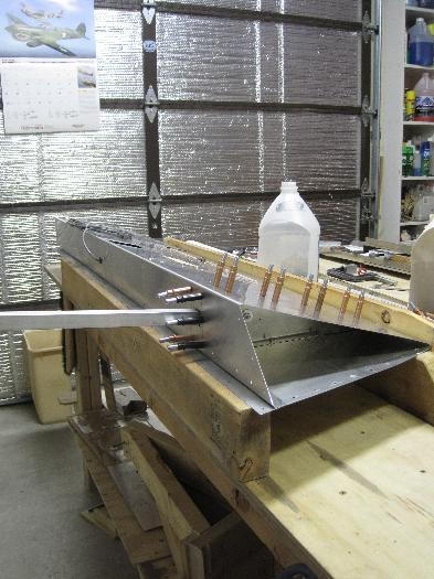
R Aileron counter-balance arm & ribs
|
|
Aileron with balance arm clecoed in place
|
|
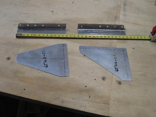
Gussets and horn reinforcments
|
|
|
|
|
|
|
|
|
Copyright © 2001-2025 Matronics. All Rights Reserved.
|