
|

|
|
|
Wendells RV-6A
|
Date: 1-1-2014
|
Number of Hours: 4.00
|
Manual Reference: GPS Antennas
|
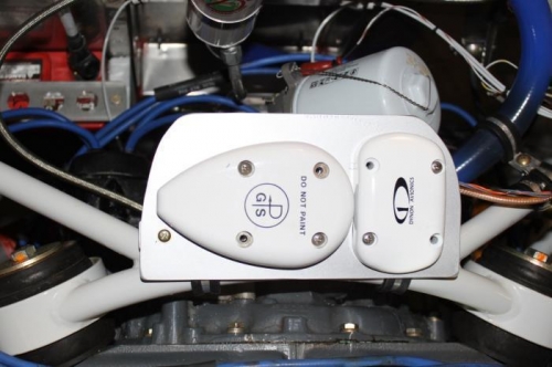
Brief Description: GPS Antenna Tray FWF
|
|
Benefits are no external drag, no need to run antenna wiring from aft of spar to forward of spar, no clutter sitting on top of dashboard, uses existing through-the-firewall wire routing.
Supplies: 2 DWG-14 adel clamps. 1 .063 angle 7 3/4 long. 1 mounting tray .063 4" x 7 3/4". 9 nutplates #8. 2 ea #8 flush screws,washers, metal locknuts. 8 #8 machine screws to mount GPS pucks (Garmin gave me 4, Dynon did not. Need to get some longer SS ones.). 1 #8 pan head machine screw.
Mark one hole for each antenna, drill that hole #19, drill a 5/8 center hole for wire access, mount using that one hole and then use the antenna to exactly locate the remaining holes. Everything will then fit perfectly. To drill the nutplates I just screwed a machine screw into the nut plate to tighten it to the tray and match drilled the nutplate 3/32 holes. Countersink the 3/4 angle for 2 flush screws to attach to the 2 adel clamps. If you plan ahead, 4 of the antenna puck mounting holes can use the 3/4 angle for nutplates. Crimped a TNC connector to the RG400 and cut off a 7 ft length to connect at the GTN750 with a BNC connector there. Primed, painted and mounted. Secured antenna wires to engine mount with adel clamps, then through the firewall with the rest of the wire.
|
|
Garmin says minumum 6 1/2 feet antenna cable for proper dB loss.
|
|
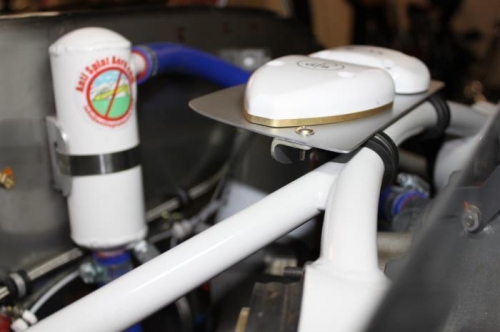
Mount angle to adel clamps 5" apart 1st. They hide under the tray. Then tray to angle.
|
|
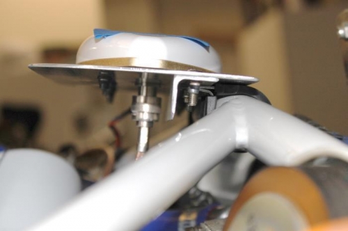
Forward row of antenna screws use nutplates in the angle for added stiffness. It's a real stable mount
|
|
|
|
|
|
|
|
|
Copyright © 2001-2024 Matronics. All Rights Reserved.
|