
|

|
|
|
Wendells RV-6A
|
Date: 3-6-2014
|
Number of Hours: 3.50
|
Manual Reference: Baffle Rods
|
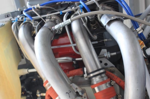
Brief Description: Install Engine Baffles 17
|
|
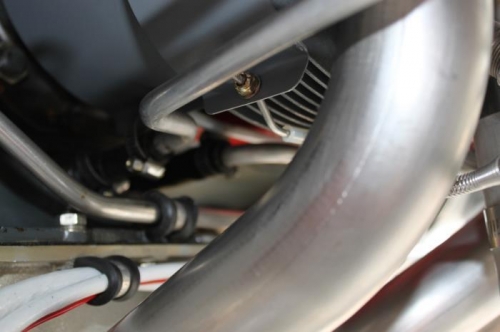
I decided, like in other situations, just do what the plans call for. I made 4 connecting rods from the provided stainless rod, cut to rough dimension, bent all ends in accordance with plans, threaded all ends with 6/32 die and added flexible brake tubing over the rods to keep them from rubbing against the oil return tubes and the lower middle engine baffles between cylinders. Two things. Don't worry about getting the brake tubing over the curved and threaded ends. Start it. Heat it with heat gun for a couple inches above the tight bend area and it gets pliable enough to move over the finished rod as you push on the end of the tube. Repeat it and it just goes on nicely while your vise holds the rod. Before threading the rod, taper the end somewhat (I used the 6 inch fine sanding disk on my bench belt sander). Not like a spear, but tapered for 1/8 inch so the die can start on it. When done, just blunt sand the tip back so its flat. I also had some Lycoming 6/32 nuts and I threaded one to reside behind the installed rods up against the inside of the baffle flange. So outside to inside its locknut, 1-2 filed washers, baffle, washer, Lycoming lock nut. The two nuts tighten against each other for added firmness against the baffle.
|
|
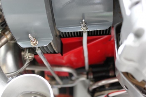
Filed edge of 6/32 washers flat to avoid digging into the baffle inside edge.
|
|
I added one inch to the plan dimension to account for tapering the rod ends for die cutting.
|
|
Rods still a little longer than plan with some extra threads. Personal taste....
|
|
|
|
|
|
|
|
|
Copyright © 2001-2024 Matronics. All Rights Reserved.
|