I finally decided on the location for the ground bus so I drilled and installed nut plates to the cross brace behind the instrument panel. I then lace tied five 2 AWG wires that will go from the firewall ground to the instrument panel ground bus, which is just a 37 pin connector with all the pins soldered together on the back side. I picked the ground bus up from the AeroElectric Connection.
After tying the wires I attached spade connectors the go to the firewall ground tabs and then pulled the wire to the instrument ground bus and installed the D-sub pins This ground bus now makes a convenient location for instrument panel items to be grounded. The wire for an item gets pinned into the connector, since all pins are interconnected by the soldered back they current finds it way down the 5 wires that attach to the firewall ground. That Bob Nuckolls at AEC is pretty smart cookie.
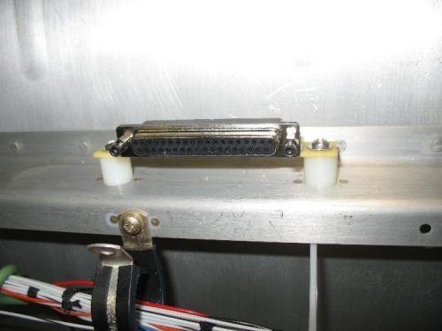
Ground bus on cross beam behind the panel
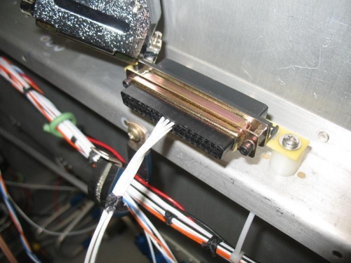
These 5 wires carry the return current to the firewall ground tabs
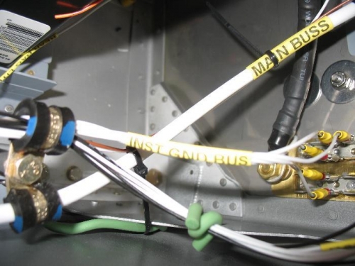
Five wire bundle attached to the ground tabs at the firewall