Brief Description: Install electric aileron trim brackets and rod
I am at a stand still as far as the flight controls are concerned since the next step is to install the control column in the plane and connect up all of the push rods. This will do me no good since I need the tail surfaced on to make any adjustments to the push rod, so I guess I will have to get to that soon. What I was able to do was install the components of the electric aileron trim.
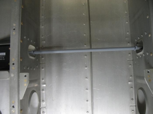
Once again the pre-punched kit made life easy. The aileron trim instructions tell you to use a template to drill holes for the servo bracket as well as but out an opening for the slide rod. Well the kit already has an oval hole and some key holes for mounting and drilling the brackets.
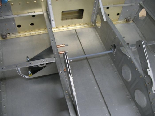
The way the trim works is the servo is anchored on one side and an aluminum tube is attached to the servo, the other side of the tube is supported by a bushing and just slides in and out. The slide rod gets two cotter pins through the center which will act as anchor points for a spring (one each side) that will attach to a spot on the control column (this attach point is already on the control column and powder coated). As the servo moves it adjust the stick left via the spring by pulling the control column. This was a very easy piece to install, I am glad I went electric.
The last thing I did today was rivet on the forward nut plate for the F445 flap control anchor block. I was missing the required K1000-3 nut plates and they came in a few weeks ago.
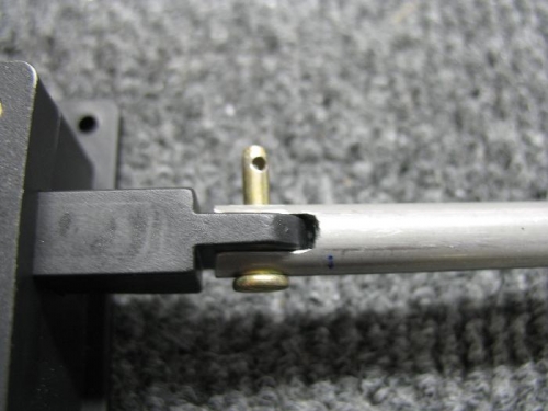
Tube must be notched to fit servo
The holes in the floor ribs are stadard on the kit now along with a few key hole for brackets
Cotter pins on left and right get a spring connected from the pin to the control column