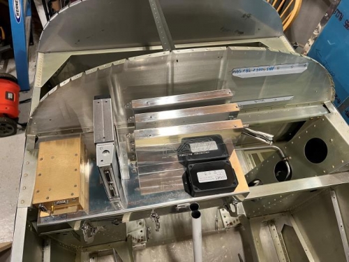
I worked on fixing my mistakes today and made progress on planning my avionics install. I test drilled holes in one of my other scrap panels to check spacing on the switches and CBs. They worked out! I moved on to laying out the avionics shelf. Everything will fit but it's fairly tight. I'm planning to build a tray for the VAL radios to slide into. Dimensions for the panel layout are below.
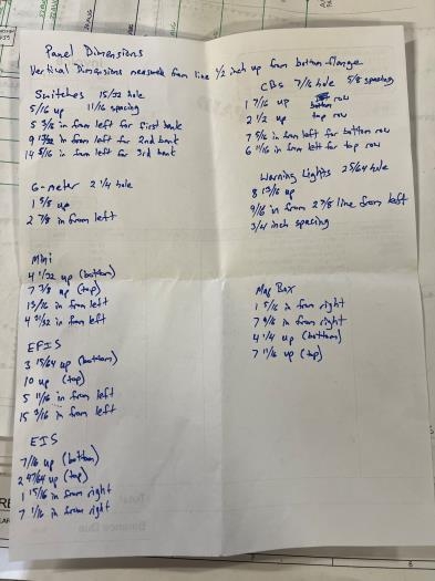
Panel Dimensions
Vertical Dimensions measured from line 1/2 inch up from outside of bottom flange.
Switches - 11/32 hole diameter 11/16 spacing 5/16 up 5 3/8 in from left for first bank 9 13/32 in from left for second bank 14 5/16 in from left for third bank
CBs - 7/16 hole diameter 5/8 spacing 1 7/16 up (bottom row) 2 1/2 up (top row) 7 5/16 in from left for bottom row 6 11/16 in from left for top row
Warning Lights - 25/64 hole diameter 3/4 inch spacing 8 13/16 up 9/16 in from 2 7/8 line from left
G-Meter - 2 1/4 hole diameter 1 5/8 up 2 7/8 in from left
Mini-X 4 1/32 up (bottom) 7 3/8 up (top) 13/16 in from left 4 31/32 in from left
EFIS 3 15/64 up (bottom) 10 up (top) 5 11/16 in from left 15 3/16 in from left
EIS 7/16 up (bottom) 2 47/64 up (top) 1 15/16 in from right 7 1/16 in from right
Map Box 1 5/16 in from right 7 9/16 in from right 4 1/4 up (bottom) 7 11/16 up (top)
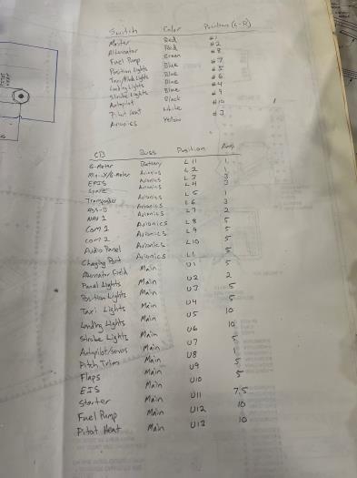
Switch Positions
Switch Color Position (L-R) Master Red #1 Alternator Red #2 Fuel Pump Green #8 Position Lights Blue #7 Taxi Lights Blue #5 Landing Lights Blue #6 Strobe Lights Blue #4 Autopilot Black #9 Pitot Heat White # 10 Avionics Yellow #3