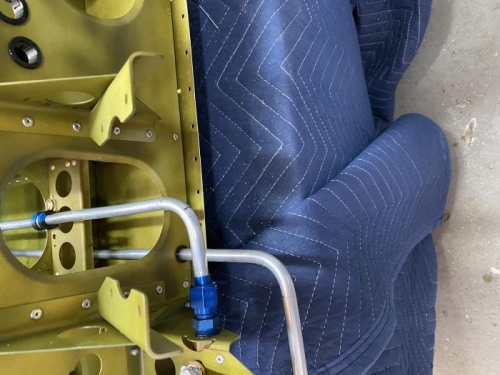
Installed the VA-265 and the T-01233 into the bottom of the fuel tank per 26iS and figure 3 page 27iS-04. Fabricated the F-12127K from 25 1/4in piece of straightened ATO-035x3/8 tubing. Measured 21/32 in from the tank end of the tube and marked the end of the bend line then measured 1 5/16in from the tank end of the tube and marked the start of the bend line. Flared the tank end of the tube then made the 38 degree bend per figure 2 same page and view A-A. Placed nut and sleeve over the oppostie end of the tube. Slide the sleeve against the flare. Made the 90 degree bend to the valve end per same figures. Placed nut and sleeve over the valve end of the tube and flared the valve end. Installed the F-12127K per figure 3 same page and installed a MS21919DG6 clamp around the fuel line and attached it to the F-01206F-2 using an AN525-10R8 screw and NAS1149F0363P washer. Connected ends to the VA-265 and right side of the Fuel Valve Bracket Assembly.
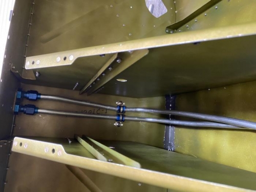
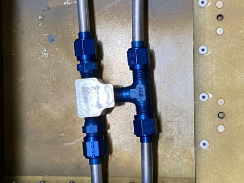
Put sleeves and nuts on the F-12127B & C and flared both ends. Installed MS21919DG6 Clamp to the F-12127B & using 2 AN525-10R7 per figure 1 page 27iS-05 & -06 and attached to the AN837-6D per same figures. Attached both lines to the Bypass Fitting Assembly.
Final Drilled 5/16 the holes in three of the F-01276C-1. Installed the three drilled F-01276C-1 with the oval recesses on the right side per figure 1 page 27iS-07.