Seperated the F-1287J Doublers from the F-1287A-1 Servo Tray with the Band Saw and file and deburr parts.
Marked and separated the F-1287D-L & -R Clevis Plates with the band saw, filed and deburred parts.
Fabricated the F-1287G and F-1287H Spacers from AT6-058 x 5/16 aluminum tube per dimensions: F-1287G 37.3mm, F-1287H 22.2mm
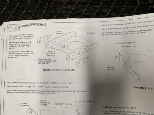
Riveted the F-1287J doublers to the F-1287A-1 Servo tray with (4) LP4-3 Rivets with the manufactured ends inside the servo tray per figure 1 page 11iS/U-06
Final Drilled 1/4" and deburred the pivot holes in the servo tray and in the F-1287C Link per the calls outs in figure 1 and 3 same page.
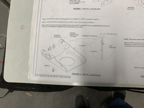
Inserted the small plastic snap bushing (SB187-2) into the opening in F-1287A-1 as shown in figure 2 same page.
Inserted the two polymer bushings (TFI-0304-04) into the F-1287A-1 servo tray as shown in figure 2 same page. Filed the polymer bushings per the dimensions given in figure 2 same page.
Deburred and flattened the F-1287C Link as shown in figure 3 same page, then inserted the polymer bushing (TFI-0304-04) into the F-1287C Link same figure same page. Filed the polymer bushing to the dimensions in figure 3 same page.
Primed all parts with Zinc Phosphate Aviation Primer
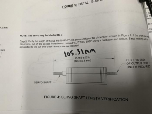
Verified the length of the ES MSTS-B6-7T-165 servo shaft per the dimensions shown in Figure 4. Length was 105.31mm and within tolerance.
Strung the wires from the ES MSTS-B6-7T-165 through the snap bushing per figure 1 page 11iS/U-07. Installed the Pitch Trim Servo (ES MSTS-B6-7T-165) to the F-1287A-1 Servo Tray using (4) AN526-632R8 screws, (4) NAS1149FN632P Washers, and (4) MS21042-06 nuts per figure 1 same page.