Brief Description: Stabilator Assembly Attachment to Tailcone
Removed AN4 bolt from both stabilator hinge brackets.
Made a mark on the Top of the WD-1223 Counterbalance Arm near the spar attachment end. Coated the bare steel section of the WD-1223 counterbalance arm with grease.
Attached the R-1014 Counterbalance Weights to the arm with (2) AN3-17A bolts, (4) NAS1149F0332P Washers, and (2) MS21042-3 nuts.
Inserted the WD-1223 Counterbalance Arm into the Stabilator Assembly at a 90 degree rotation from the correct installed location and made sure the counterbalance arm was within both WD-1222 Counterbalance Brackets.
Inserted the counterbalance weights through the hole in the aft bulkhead of the tailcone assembly. Then rotated the counterbalance arm to the proper installed located as indicated by the Top Marking made above..
Installed the counterbalance arm using (2) AN3-14A bolts, (2) NAS1149F0363P Washers, and (2) MS21042-3 nuts.
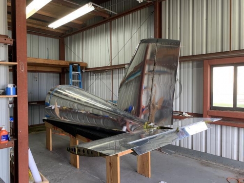
Installed the stabilator assembly to the tailcone assembly using (2) AN4-12A bolts with (6), (3) on each side, AN960-416L Washers. Ensured glued washers (included in these counts) from page 10-05 were still in place.
Verified Stabilator Assembly movement to make sure it swings freely, travel in both directions was only limited by the hinge stops contacting the F-1211C hinge brackets.
Using the hinge pins from page 8-3, step 5, frabricated two hinge pins per the dimensions given in figure 1 page 11iS/U-04. Including filing a dull point at the one end and bent the other.
Installed the left and right AST Assemblies to the stabilator Assembly using the fabricated hinge pins per figure 2 same page.