Brief Description: V-Stab Assembly and Rudder Attachment
Removed the VS-1204 Fwd Skin, the Lower Hinge Assembly and the hinge hardware from the V-Stab Assembly.
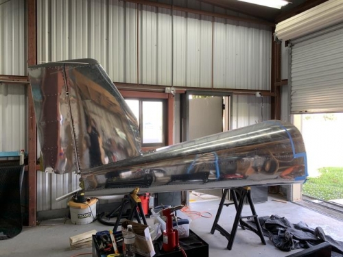
Placed a piece of paper on the aft end of the tail cone to protect the skin surface from scratching. Verified the bottom edge of the V-Stab Assembly for deburring.
While routing the AV-532L Cable from section 42PiS, attached the rear spar of the V-Stab Assembly to the Tailcone Assembly using the lower four fasteners: 4 AN3-5A bolts, 4 NAS1149F0363P Washers, 4 NAS 1149F0332P Washers, did not tighten. Attached the front spar of the V-Stab Assembly to the tail cone assembly using 4 AN3-4A bolts and 4 NAS1149F0332P Washers but did not tighten.
Installed the Lower Hinge Assembly on the V-Stab and the Tailcone Assembly using 4 AN3-5A Bolts and 4 NAS1149F0332P Washers. Tightened all V-stab Assembly attach bolts to prevent V-Stab Assembly movement.
Attached the Rudder Assembly to the V-Stab Assembly using 2 AN3-10A Bolts and 8 (4 each) NAS1149F0363P Washers. Verified Rudder travel in both directions is only limited by the rudder horn contacting the rudder stop showing in figure 2, detail C-C page 11iS/U-02.
Final Drilled #12 the attach holes in all of the R-1014 Couterbalance Weights by Final Drilling the Aft hole, using an AN3 bolt as a pin to pin the weight to the WA-1223 Couterbalance Arm, then final drilled using the forward hole in the arm as a drill gauge, per figure 2 same page.
Skipped Step 8 per instructions since we will be installing the Fiberglass tip fairings in Section 12A.