Removed and Trimmed excess material from the recessed areas of the R-1206 Rudder Tip Fairing and the VS-1213 V-Stab Tip Fairing per figures 1, 2, and 3 page 12-02.
Trimmed the VS-1213 V-Stab Tip Fairing to within 1/8" of the aft scribe line per figure 3 same page.
Placed the R-1206 Rudder Tip Fairing onto the Rudder Assembly and trimmed to flush against the top edge of the main skin.
Held R-1206 Rudder Tip Fairing in place and match drilled #30 the holes from the R-1201 Main Skin into the Rudder Tip Fairing. Cleco'ed each hole before drilling the next.
Remove and deburred, then re-cleco'ed.
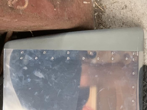
Placed the VS-1213 V-Stab Tip Fairing onto the V-Stab Assembly. Trimmed and fit the VS-1213 so the edge of the recessed area of the v-stab tip fairing was flush against the top edge of the VS-1201 Main Skin per figure 1 page 12-03
Holding the VS-1213 V-Stab Tip Fairing in place match drilled #30 the holes from the VS-1201 Main Skin into the VS-1213 V-Stab Tip Fairing as shown in figure 1 same page. Cleco'ed each hole before drilling the next. Removed and Deburred VS-1213.
Marked and trimmed VS-1213 V-Stab Tip Fairing to ensure a smooth transition to the VS-1201 main skin.
Temporarily Attached the Rudder Assembly to the V-Stab Assembly
Placed the VS-1213 and trimmed the aft edge to ensure at least 1/8" clearance between the V-Stab Tip Fairing VS-1213 and the Rudder Assembly through out the entire travel path of the Rudder. Smoothed the edges of the VS-1213 and re-cleco'ed in place.
Skipped step 2 per 42Pis installation. Removed Rudder Assembly from the V-Stab Assembly and riveted the R-1206 Rudder Tip Fairing to the Rudder Assembly using 12 LP4-3 Rivets per Figure 1 page 12-04.