Separated F-1238 into F-1238-L & -R, deburred per figure 1 reference page.
Hooked the F-1279-L & -R Upper Left and Right Skins J-Stiffeners into the cutouts of the F-1208, F-1209, and F-1210 Frames and cleco'ed the upper left and right skins to the frames and the F-1280-L & -R Left and Right Side Skins as shown in figure 2 reference page.
Cleco'ed the F-1238-L & -R Snap Bushing Brackets to the F-1279-L & -R Upper Left and Right Skins as shown in figure 2 reference page.
Match Drilled #30 the holes called out in the F-1279-L & R upper left and right skin j-stiffeners into the F-1238-L & -R snap bushings. Removed, drilled a #30 hole in the F-1238-R snap bushing per section 42Pis page 42PiS-07 step 1 for the Garmin IFR Option. Deburred and re-cleco'ed in place.
Riveted the F-1238-L & -R Snap Bushings to the F-1279-L & -R upper left and right skins using 5 each LP4-3 rivets.
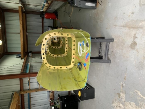
Inserted 1 each SB750-10 snap bushings into the F-1238-L & -R Snap Bushing Brackets called out in Figure 2 reference page.
Routed a string from the forward end of the exisitng structure to the F-1211 Assembly. The string was routed through the F-1238-L Snap Bushing Bracket out through the left rudder control cable cutout, then back through the right rudder control cable cutout, through the F-1238-R Snap Bushing Bracket as shown in figure 2 reference page. Returned the string to the forward of the existing structure and taped both ends of the string to the inside surface of the bottom string and labeled the tape "Rudder Control Cables"