
|

|
|
|
Dan's Web Site
|
Date: 5-28-2007
|
Number of Hours: 0.50
|
Manual Reference:
|
Brief Description: Install P-Lead's / Grounds to Ignition Switch
|
|
Today I hooked up the P-leads to the ignition switch. The P-lead for the right mag also has a jumper plate from the "R" terminal on the switch to the ground terminal right next to the "R" terminal. This is to ground the right mag on start-up so that only the left mag is used to start the engine since the left mag has an impulse coupler so that it won't fire the normal 20-25 degrees before top dead center (BTDC) and cause a kick back on start-up. The impulse coupler causes the left mag to fire at TDC instead. Once the engine is started, the left mag's impulse coupler is disengaged, the right mag is turned on, and both mags fire at 20-25 degree's BTDC.
So,,,the P-leads were connected to their respective "R" and "L" terminals on the ignition switch, the "R" terminal is jumpered to GRD, and the ground pigtails (solder sleeves) on the P-leads were both connected to the center GRD terminal on the switch.
Once the P-leads were wired to the ignition switch I drilled dedicated holes in the sub-panel and firewall, installed snap bushings and routed the P-leads to the mags. I want to keep the P-leads isolated from the sensor and power leads to prevent any potential noise in my electrical system.
|
|
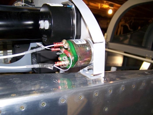
P-leads, grounds, and jumper wired to ignition switch
|
|
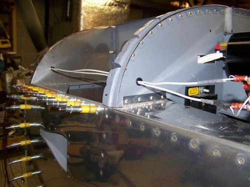
P-leads routed through their own holes in sub-panel and firewall
|
|
|
|
|
|
|
|
|
Copyright © 2001-2024 Matronics. All Rights Reserved.
|