
|

|
|
|
Marlins Web Site
|
Date: 2-1-2023
|
Number of Hours: 3.00
|
Manual Reference: N/A
|
Brief Description: Install Engine EGT & CHT Sensors (Cont.)
|
|
I thought I would show a picture of the #3 Exhaust and Cylinder EGT & CHT Sensors. This was where I cross-threaded the CHT Senser. The 2nd picture is the completed wiring to the Grand Rapids EIS and the LASAR Ignition System. On the left side of the 3rd picture, you can see two “pig-tail” wire terminals. When I started installing the EGT and CHT sensors, I had ten wires coming through the firewall and only eight places to connect to the EGT and CHT sensors. I had to dig out my old wiring schematics from 10 years ago to figure out what a white and purple set of wires where connected to. As it turns out, the LASAR system wiring says to connect these wires to the cylinder the gets the hottest, first, when you are flying so it can automatically adjust lean-of-peak. So, my question was, “How the heck do you know which engine cylinder this will be until you run the danged engine?” I surmised it’s not going to be the #1 or #2 cylinders, because they are getting the most, and coolest, ram-air from the cowl inlets. It’s more logical either the #3 or #4 cylinders will heat up first. I’m guessing it’s going to be the #4 cylinder because I have this big, ‘honking’ oil cooler inlet that will suck out a bunch of the air before it gets directed down to the #4. BUT, just to be sure I’m not wrong, I installed two pig-tail wire terminals to the #3 (aand as you will see later) #4 CHT Sensor Wires.
|
|
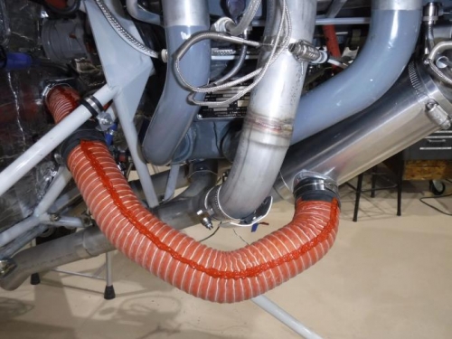
#3 EGT & CHT
|
|
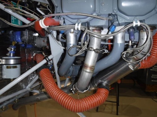
Right Side EGT & CHT Wiring
|
|
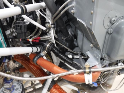
Wiring to EIS and LASAR??
|
|
|
|
|
|
|
|
|
Copyright © 2001-2024 Matronics. All Rights Reserved.
|