
|

|
|
|
Marlins Web Site
|
Date: 9-12-2022
|
Number of Hours: 6.00
|
Manual Reference: OP-40
|
Brief Description: Install Baffling
|
|
It’s been 5 months since I last worked on the -7A. In May, I had to deal with flooded crawl-space and destroyed bathroom at my home. Then, to top things off, I ruptured my left bicep unloading a shower door from Home Depot. So, between a complete remodel and recovery from surgery, the airplane gathered a lot of dust. It’s finally time to start building the engine baffles. Several months ago, I painted all the baffle parts with Stuart Systems Epoxy paint. Today, I sorted and arranged all the baffle parts and did my best to try visualize how all the baffles were tied together as a system. There is a good reason they are named “baffles”…the system is pretty complex and there is a lot of fitting/finessing pieces together in a specific order or you end up drilling out rivets. For the first time since I started working on this airplane, Van’s actually updated their baffle plans for an IO360-M1B engine. The plans are fairly good, but each of the actual baffle parts require a significant amount of trimming, cutting, drillings, and fitting. In many cases, the parts don’t fit at all and I will have to fabricate parts as I go. VAN’s OP-40 plan has the builder start with the aft-left baffle where the oil cooler is attached. It’s not clear to me why VANs didn’t update these parts and issue reinforcing bracing. Virtually, everyone who used VAN’s baffles/plans for the RV-6 through RV-8 oil cooler installation, as designed, have cracked their baffles on the oil cooler outer flange (see pic 3).
|
|
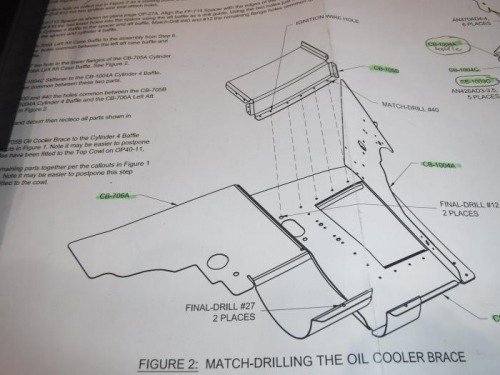
Oil Cooler Baffle Cylinder #4
|
|
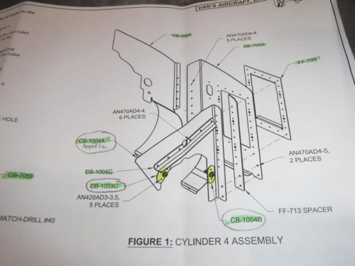
Left Aft side Baffle Cylinder #4
|
|
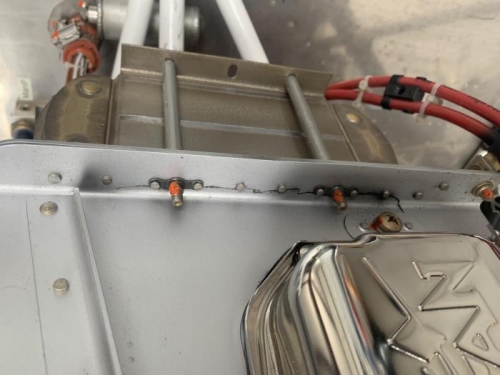
Where cracks occur
|
|
|
|
|
|
|
|
|
Copyright © 2001-2024 Matronics. All Rights Reserved.
|