
|

|
|
|
Marlins Web Site
|
Date: 4-21-2022
|
Number of Hours: 5.00
|
Manual Reference: N/A
|
Brief Description: Fabricating a Throttle Control Mounting Bracket
|
|
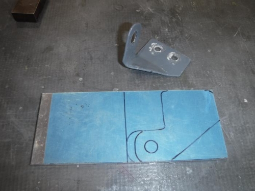
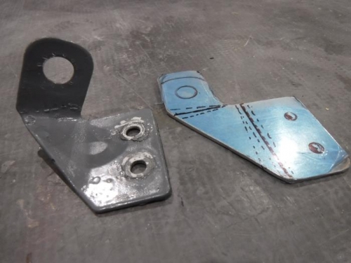
I started by removing the VAN’s bracket I removed several months ago and re-shaped because the original instructions were not updated and didn’t correspond to the location the throttle control cable has to be routed through the firewall and under the engine. Several months ago, when I realized VAN’s plans were screwed up again (for the 100th time), I had to purchase control extensions and modify the mounting bracket to fit the location on the IO360-M1B engine. I disassembled the control assembly, added the extensions, them made everything fit…except I didn’t have the correct Vetterman’s Crossover Exhaust system …the one VAN’s sent me and would not take back in exchange for the correct one, was actually for an RV-8 tail-dragger. Now that I have a correct exhaust system and $1,100 later, my modified Throttle Control Mounting Bracket places the rubber seals on the control right on the hot exhaust pipe. I guess you can tell, I’m still not quite over the exhaust thing. These pics show the mount refabrication process. First I laid out the outline on some raw aluminum stock, taking into account the distance required for the bends. Next, I cut out my layout on the band saw and drilled holes where the parts were curved. Then I made the multiple bends and angles using my bench clamp and a metal bender. Finally, I drilled the holes, slightly oversized to accommodate any later adjustments. The last picture is the old and new. You can’t see it well in the picture, but the new hole where the control passes through is about ½” offset closer to the engine block to make enough clearance for a heat shield on the exhaust.
|
|
Fabrication Process
|
|
Bend Lines for bends
|
|
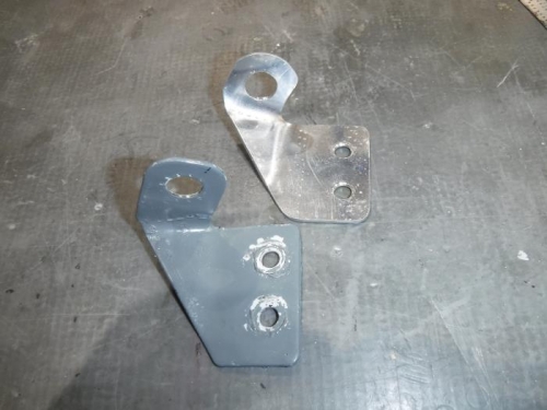
Old and New
|
|
|
|
|
|
|
|
|
Copyright © 2001-2024 Matronics. All Rights Reserved.
|