Brief Description: Clamped Wires/Finished Alternator Wire to CB
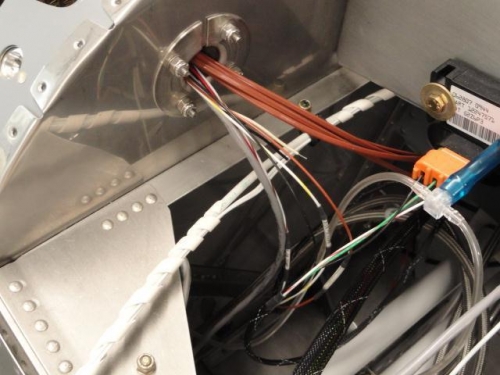
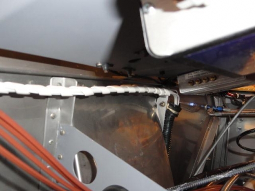
The P3 and K1 wires were spiral-wrapped together, along with the P1 wire, coming out of the plastic tubing and then clamped to the top bracket along the firewall on the left side.
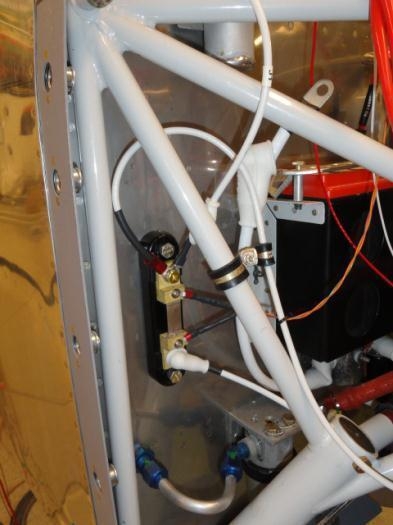
The #8 wire from the top terminal on the ammeter shunt going to the alternator CB was run thru the instrument sub-panel and then the terminal was crimped on the end. Heat-shrink was applied and the terminal was screwed to the CB. The CB had another unused terminal with the notation "To ALT" screwed to it on the other terminal, which was removed. The wire was clamped to the engine mount.
The alternator is now wired to the ammeter shunt, which is wired to the master relay/battery and to the alternator CB.
The P1 wire coming off the master relay and going thru the firewall needs to be removed and not used. I had installed it using Van's drawings, OP-10 and OP-12. The use of the ammeter shunt and the Aerotronics panel precluded the use of the P1 wire.
The P1, P3 and K1 wires spiral-wrapped and clamped to the firewall