
|

|
|
|
RV-6A - GBC
|
Date: 1-1-2011
|
Number of Hours: 2.00
|
Manual Reference: Sect 8
|
Brief Description: Wing sweep & incidence angles
|
|
Okay - deviation from the 'procedure' in the manual to establish a measurement of wing sweep. The goal of the procedure is to determine that the LE of each wing is perpendicular to the longitudinal axis of the fuselage. A series of phyiscal measurements using tape measures and plumb-bobs is outlined. This is an alternative design for the same end goal, using precision lasers to measure alignment. It is my understanding that modern aircraft construction is accomplished this way by major manufacturers, too, (conceptually).
I leveled the fuselage as required, laterally and longitudinally, with a digital level to 0.0 degs (I heard that Vans personnel use a bubble level and us 'builders' are striving for digital perfection.) Then I set up two opposing laser systems. The first is a 3--axis laser level with a bubble, XYZ, at 90 degree angles. Each axis is indicated by a laser 'projected dot'. The second laser is a self-leveling 2-axis unit that projects a 'line' on each of the planes, vertical and horizontal.
The 3rd axis (Z) of the first unit is not needed, so I'm using the X and Y projections, one from the center of the F-604 area of the fuselage toward the center line of the tailcone. The other projected dot is toward the left wingtip, along the seam of the LE skin on the main spar. I affixed a 'target' on the wingtip to see the dot and rough in the alignment with the opposing laser.
Only the vertical plane of the 2nd laser is required, to project a line along the seam of the LE skin on the spar back to the first laser in the fuselage area. (see the next entry for the result).
|
|
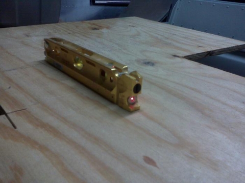
3-axis laser level
|
|
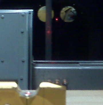
Projected to ctr of tailcone
|
|
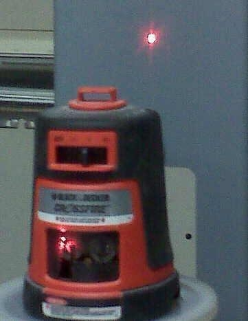
Self leveling 2-axis laser
|
|
|
|
|
|
|
|
|
Copyright © 2001-2024 Matronics. All Rights Reserved.
|