
|

|
|
|
RV-6A - GBC
|
Date: 1-1-2011
|
Number of Hours: 1.00
|
Manual Reference: Sect 8
|
Brief Description: Wing sweep & incidence angles - continued
|
|
(Cont'ed - 1.1.01) ---
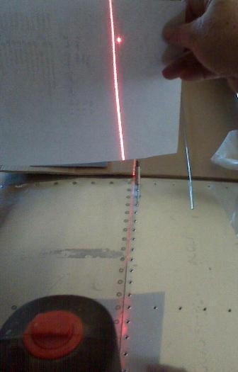
Holding a sheet of paper (translucent) over the wing spar, near the wingtip (Photo), it is possible to determine the direction and magnitude of the sweep adjustment needed. In this case, approx 1/8th inch aft on the wingtip. After that movement, it will be REQUIRED to re-aligned the fuselage laser before further movement.
The X-Y right angle of the first laser could be accomplished from numerous points, but the intersection of the vertical plane laser from the wingtip, aligned with the LE skin seam on the main spar MUST be used to determine the position of the X-Y angle location. There is ONE and ONLY ONE position where the oppsoing lasers intersect, and that should be a precise measure of the sweep of the leading edge. The seam is a 'proxy' of the parallel line of the leading edge. Can be confirmed, but would be illogical to assume anything else in this construction and wing design.
This process can be flip-flopped for the alignment of the right wing, independently and the result should be two perfectly aligned wings perpendicular to the center (longitudinal axis) of the aircraft. Like any procedure there is a chance of error through sloppy workmanship. Given the precision required for setting the sweep angle, it is reasonable to conclude that this procedure should meet or exceed the threshold of acceptable tolerance. It is possible double check this procedure with the plumb-bob method, too.
|
|
Alignment difference
|
|
|
|
|
|
|
|
|
Copyright © 2001-2024 Matronics. All Rights Reserved.
|