Brief Description: Backing plate-spacer assembly/Camlock mount strip
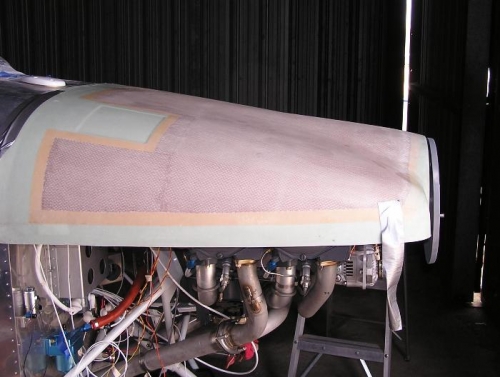
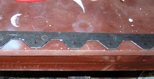
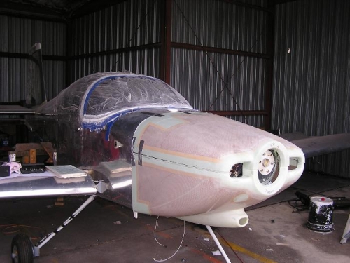
We wanted to mount the spacer, backing plate and the prop today but didn't have enough info to do it. We finally called Sensenich and they told us the relationships that needed be used. There is a 1 on the spinner and it mounts on the 1 prop blade. The prop then mounts on the ring gear so that the prop is at 11 o'clock with the #1 cylinder at top dead center. We had called Van's and others before we found this out. I don't have a spark plug wrench to pull the top plugs to determine #1 cylinder at TDC. So maybe tomorrow I will be able to mount the prop but if I can't we can mount the spacer/spinner backing plate well enough to get our relationship to the top cowl. This approximate location can be seen in Image #1. Image #3 shows a rough fitting of the upper and lower cowl but much must be done before this is finally finished but it was fun to see it in place. I have decided to us Camlocks from Milspec Products to attach the top cowl to the firewall. I had ordered 12 camlocks for this but today when we laid it out we will need 14 so I called and ordered 2 more. We got the 30% discount in a group buy organized on the Van's Air Force Forum. In Image #2 you can see the mounting strip we made from a 2" wide 060" aluminum strip. This will be riveted to the fire wall and then drilled for the Cam locks. I have noticed that many use these fasteners on the top instead of the hinges. We will use hinges on the sides and the bottom.