
|

|
|
|
My RV-8 Build Log
|
Date: 9-28-2014
|
Number of Hours: 3.00
|
Manual Reference:
|
Brief Description: IBBS Installation
|
|
Finally mostly finished with building the rudder, started building installation brackets for the TCW Integrated Backup Batter System (aka IBBS). The IBBS will provide power to the avionics should the primary electrical system fail, and also provide power to the EFIS during engine start for the EIS displays (oil pressure, etc…)
• Cut four 4” aluminum 2024-T3 aluminum angle to make two brackets for securing the IBBS.
• The IBBS does not have any instructions for how to secure the battery to the airframe, but based on its weight, there is no doubt it must be well secured. TCW does indicate the battery needs to be installed in a serviceable location.
• I decided to install the IBBS under the right console cover, where the connector and wires will be easily routed through the right gear leg tower, like the wing lighting and UBS power.
• Created two brackets from the previously cut aluminum angle, riveted using AN470 4-7 rivets.
• Located the holes for attaching the IBBS to the two brackets, drilled using #40, then #30, final drilled with #10 for the R10 flush screws.
• Attached K1000-3 nut plates to the two brackets for the four #10 holes, secured using AN3-4 bolts.
• Used the nut plates to locate and drill #40 holes for attaching the nut plates.
• Disassembled, deburred all holes except the top side of the #40 holes which are to be counter sunk for AN426 rivets.
• Countersunk the #40 holes for the AN426 rivets for attaching the K1000-3 nut plates.
• Clecoed the angles together, installed the AN470 rivets to create the two brackets.
• Clecoed the nut plates on the brackets and riveted using AN426 rivets.
• To locate the IBBS in the fuse under the right console cover, attached the brackets using three AN3 bolts, and attached the power cable. The IBBS has countersunk holes for R10 flush screws.
• Located the IBBS, ran the power cable (wire bundle) through the right gear leg tower to make sure removing the connector is possible, and it is possible to locate the #30 holes needed for the LP4-3 blind rivet
|
|
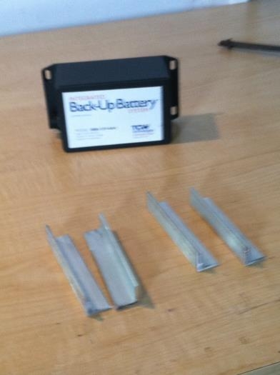
IBBS and four 4" Angle
|
|

IBBS mounted to brackets
|
|
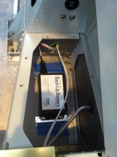
IBBS located under right console cover
|
|
|
|
|
|
|
|
|
Copyright © 2001-2024 Matronics. All Rights Reserved.
|