
|

|
|
|
My RV-8 Build Log
|
Date: 9-21-2014
|
Number of Hours: 6.00
|
Manual Reference:
|
Brief Description: Rudder - Continue Build
|
|
Continued with building the new rudder…
• Measured and cut the rudder horn spacer from .037 2024 aluminum (3.5” x ½”). Deburred edges
• Measured and cut two rudder bottom cap strips, .037 2024 aluminum (14.5” x 1 1/8”). Deburred edges.
• Clecoed the rudder spar, bottom rib, rudder horn, horn support bracket, the 3 reinforcement plates for the rod end bearings, including nut plates together, matched drilled for the AD470 rivets.
• Clecoed the rudder top rib and counterbalance skin (this is the part that was the genesis of the new rudder), and matched drilled holes except for the rear three most holes which will be in common with the rudder skin.
• Disassembled all parts, deburred all holes and edges.
• Dimpled all holes as/if required for the top and bottom ribs, counter balance skin, spar, rudder horn brace (where in common with the bottom rib), and the bottom cap attachment strips.
• Riveted the counterbalance skin to the top rib, leaving the 3 rear most holes free.
• Riveted the bottom rib, rudder horn, rudder horn spacer, rid end bearing nut place, and reinforcement place to the spar using AN470 4-5, 7 or 8 rivets per plans.
• Riveted the remaining two nut plates and reinforcement plates to the spar.
• Riveted the top rib to the spar.
• Inserted the riveted structure into the rudder skin, clecoed one side only, and left the other side open for dabbing some RTV into the trailing edge where the stiffeners meet. – tomorrow -
|
|
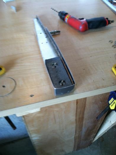
Riveting structure
|
|
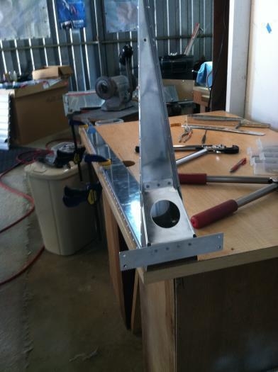
Top rib with counterbalance
|
|
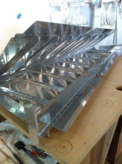
Completed Structure clecoded to skin
|
|
|
|
|
|
|
|
|
Copyright © 2001-2024 Matronics. All Rights Reserved.
|