Brief Description: Fabricate the Rudder Stop Plate
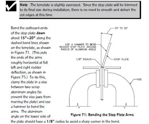
Step 60: Fabricate the Rudder Stop Plate As mentioned in the previous step, the specified rudder travel is 25° (1°) in each direction. To prevent damage to the rudder from traveling too far, a 1/8" thick aluminum rudder stop plate, with arms that contact Bulkhead C, will be riveted to the rudder yoke to limit the rudder’s travel to no more than the specified value. Lay out the pattern shown in Figure 72 on the supplied .125" X 3" X 10" aluminum sheet [25.1]. Use a bandsaw to cut out the stop plat
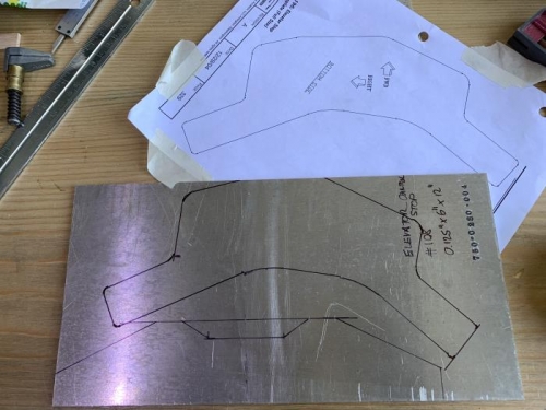
Step 174: Fabricate and Install the Elevator Control Stop Using the bevel gauge method to check, hold the elevator at its up travel limit of 23° and mark the location of the aft face of Bulkhead E onto the elevator pushrod with a felt-tip pen. Then hold the elevator at its down travel limit of 20° and make a similar mark on the pushrod. These marks will be used to position the bellcrank after the stabilizer/elevator assembly has been removed so that the elevator limit stops can be adjusted. Disconnect the elevator pushrod from the control horns and remove the stabilizer/ elevator assembly from the airplane. Next, disconnect the control cables from the elevator bellcrank by removing the clevis pins that secure the ends of the cables to the control cable attach tabs. Remove the bellcrank from the airplane by disconnecting the pushrod and removing the pivot bolt. Remove the cable attach tabs and associated hardware from the bellcrank. Figure 196 is a full-sized template of the elevator stop plate. Use a bandsaw to cut the plate out from the .125" X 6" X 12" aluminum sheet [108]. File or sand the edges smooth.